Configuration Methods
- Application Limitations
- NAT Network Between the iClient S100 and HWT-IVS1800
- NAT Network Between the HWT-IVS1800 and the Upper-Level Video and Image Management Platform
- NAT-based Networking of the HWT-IVS1800 and Cameras
Application Limitations
- NAT must be configured on the firewall and the network communication must be normal. There is no requirement on the networking mode (such as bypass or direct connection) that involves access through the firewall.
- The client cannot be directly connected to cameras to obtain media streams.
- In NAT networking, networks can be classified as extranets or intranets. All intranets must be connected through the same extranet for communication. For example, all campus intranets are connected through the private network, which functions as an extranet.
- When selecting or configuring a firewall, you are advised to ensure that the firewall bandwidth is twice the maximum concurrent video traffic traversing the firewall. Otherwise, the forwarding performance of the firewall may be insufficient to support a large number of burst streams, causing packet loss or delay. This will further lead to video stuttering or artifacts.
- Only compatible devices can be connected. For details, see the HWT-IVS1800 Compatibility List. If an incompatible device is connected, you can submit customization requirements or perform verification by yourself.
- In the scenario where cameras are on the intranet and registered passively:
- The iClient S100 does not allow users to add multiple cameras with the same IP address.
- Cameras to be connected through ONVIF (passive registration) must support NAT.
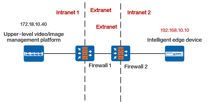
Figure 5-51 Overall network diagram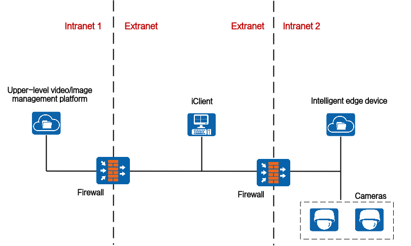
NAT Network Between the iClient S100 and HWT-IVS1800
iClient S100 on an Extranet and HWT-IVS1800 on an Intranet
Network
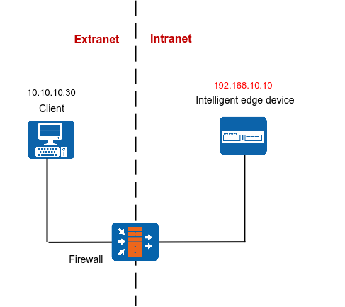
If the iClient S100 is on an extranet and the HWT-IVS1800 is on an intranet, you need to translate the IP address and port number of the HWT-IVS1800 to an extranet IP address and port number for the iClient S100 to access, as shown in Figure 5-52.
Data Plan
This section uses NAT mapping based on IP addresses and port translation as an example for data plan.
NAT based on IP address translation is relatively simple. In addition to IP address NAT on the firewall, the ports in the data plan need to be allowed in both directions. For details about how to allow ports, see the firewall documentation.
NE |
Require Configuration on the NE |
Pre-NAT IP Address |
Post-NAT IP Address |
Pre-NAT Port Number |
Post-NAT Port Number |
|---|---|---|---|---|---|
iClient S100 |
No |
- |
- |
- |
- |
Firewall |
Yes |
192.168.10.10 |
10.10.10.10 |
|
|
HWT-IVS1800 |
Yes |
|
|
|
|
Configuring NAT on the Firewall
- Go to the firewall configuration page by referring to Logging In to the Firewall.
- Configure NAT based on the data plan.
- IP address NAT:
nat server name global Post-NAT IP address inside IP address of HWT-IVS1800
- IP address and port NAT
- NAT of a single IP address and a single port
TCP: nat server name protocol tcp global Post-NAT IP address Post-NAT port number inside IP address Port number unr-route
UDP: nat server name protocol udp global Post-NAT IP address Post-NAT port number inside IP address Port number unr-route
- NAT of a single IP address and multiple ports
TCP: nat server name protocol tcp global Post-NAT IP address Post-NAT start port number Post-NAT end port number inside IP address Start port number End port number unr-route
UDP: nat server name protocol udp global Post-NAT IP address Post-NAT start port number Post-NAT end port number inside IP address Start port number End port number unr-route
- NAT of a single IP address and a single port
In the preceding commands, name indicates the unique name of the NAT server. The requirements on the server name are as follows:
- It is a string of 1 to 256 case-sensitive characters and can be a combination of digits.
- It must start with a letter or digit.
- It cannot be all, vsys, or all-systems and cannot be name, global, protocol, vpn-instance, zone, or their first several characters. For example, the value cannot be n, na, or nam.
- IP address NAT:
- Run the display current-configuration command to view the NAT configuration on the firewall and determine whether the NAT configuration is correct.

To modify the NAT configuration on the firewall, run the undo nat server name command to delete the original NAT configuration and then re-configure NAT.
- Configure a security policy on the firewall.
[FW] security-policy
[FW-policy-security] rule name rule_name
[FW-policy-security-rule-policy_sec1] source-zone untrust
[FW-policy-security-rule-policy_sec1] destination-zone trust
[FW-policy-security-rule-policy_sec1] destination-address video/image management platform IP address 32
[FW-policy-security-rule-policy_sec1] action permit
[FW-policy-security-rule-policy_sec1] quit
- rule_name: name of a security policy. You can configure multiple security policies as required.
- IP address of device in the Trust security zone: pre-NAT IP address of the intranet device. If there are multiple IP addresses, configure multiple security policies.
- Optional: Configure NAT ALG.Compared with the HWT-IVS1800+firewall NAT scheme, the firewall ALG scheme occupies fewer ports.
Configure port NAT.
By default, SIP port 5060 is used. However, GB/T 28181 uses SIP port 5080. Therefore, you need to perform this step.
[FW]acl 2000
[FW-acl-basic-2000]rule permit
[FW-acl-basic-2000]quit
[FW]port-mapping sip port 5080 acl 2000
[FW]quit
- Configure firewall NAT ALG to implement proper SIP packet forwarding.
[FW] firewall interzone trust untrust
[FW-interzone-trust-untrust] detect sip
[FW-interzone-trust-untrust] quit
- Verify that the settings have taken effect.
After the cameras are successfully registered, run the display firewall session table command on the firewall to view the session table. The following information indicates that the settings have taken effect:
Current Total Sessions : 2
sip VPN:public --> public X.X.X.X:2107-->10.10.10.10:5080[192.168.10.13:5080]
- Configure a static route to the extranet IP address (for example, 10.10.10.90) on the router, with the next hop being the intranet IP address of the firewall. In this manner, the messages returned from an extranet can be forwarded to the firewall.
In most cases, you need to contact the network administrator to configure the static route.
Configuring NAT on the HWT-IVS1800
- Log in to the OMU portal as the admin user. (
 Logging In to the OMU portal)
 - Choose System > Advanced Configuration.
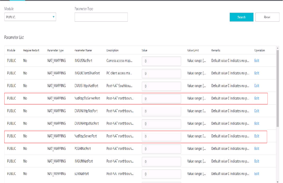
- Configure NAT information, as shown in Figure 5-53.
The parameters to be set vary depending on the scenario where the iClient S100 is connected to the HWT-IVS1800.
- If the HWT-IVS1800 deployed in single- or dual-address mode is connected to the iClient S100 only through the northbound interface, set the parameters described in Table 5-30.
Table 5-30 Parameter description
Module
Parameter
Description
PUBLIC
NNatIP
Northbound IP address of the HWT-IVS1800, which must be the same as the post-NAT IP address configured on the firewall.
NatRtspServerPort
Post-NAT northbound port number of the MU of the HWT-IVS1800, which must be the same as the post-NAT port number configured on the firewall. The default port number is 554.
- If the HWT-IVS1800 deployed in dual-address mode is connected to the iClient S100 only through the southbound interface, set the parameters described in Table 5-31.
Table 5-31 Parameter description
Module
Parameter
Description
PUBLIC
SNatIP
Southbound IP address of the HWT-IVS1800, which must be the same as the post-NAT IP address configured on the firewall.
NatSRtspPort
Post-NAT southbound port number of the MU of the HWT-IVS1800, which must be the same as the post-NAT port number configured on the firewall. The default port number is 554.
- If the HWT-IVS1800 deployed in dual-address mode is connected to the iClient S100 through both the southbound and northbound interfaces, set the parameters described in Table 5-30 and Table 5-31.
- If the HWT-IVS1800 deployed in single- or dual-address mode is connected to the iClient S100 only through the northbound interface, set the parameters described in Table 5-30.
- Log in to the iClient S100 again and add the HWT-IVS1800.
When adding a device, use the HWT-IVS1800 IP address and port number translated on the firewall.
iClient S100 on an Intranet and HWT-IVS1800 on an Extranet
Network
If the iClient S100 is on an intranet and the HWT-IVS1800 is on an extranet, you need to configure the network route and firewall to connect the iClient S100 to the HWT-IVS1800.
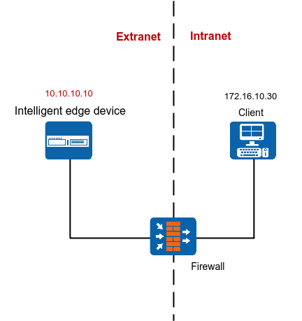
The following describes how to configure firewall NAT. On the firewall, you need to translate the IP address of the server running the iClient S100 to an extranet IP address so that they can use the HWT-IVS1800 extranet IP address and port number to log in to the iClient S100 to view live and recorded video and perform other service operations, as shown in Figure 5-54.
Data Plan
NE |
Require Configuration on the NE |
Pre-NAT IP Address |
Post-NAT IP Address |
Pre-NAT Port Number |
Post-NAT Port Number |
|---|---|---|---|---|---|
iClient S100 |
Yes |
172.16.10.30 |
10.10.10.30 |
58097, 58103, 58102 |
58097, 58103, 58102 |
Firewall |
Yes (optional) You can either configure NAT or use routers and switches to implement the network connection between the iClient S100 and video and image management platform. |
172.16.10.30 |
10.10.10.30 |
58097 |
58097 |
HWT-IVS1800 |
No |
- |
- |
- |
- |
(Optional) Configuring NAT on the Firewall
- Go to the firewall configuration page by referring to Logging In to the Firewall.
- Configure NAT based on the data plan.
- IP address NAT:
nat server name global Post-NAT IP address inside IP address of the computer running the client
- IP address and port NAT
- NAT of a single IP address and a single port
TCP: nat server name protocol tcp global Post-NAT IP address Post-NAT port number inside IP address Port number unr-route
UDP: nat server name protocol udp global Post-NAT IP address Post-NAT port number inside IP address Port number unr-route
- NAT of a single IP address and multiple ports
TCP: nat server name protocol tcp global Post-NAT IP address Post-NAT start port number Post-NAT end port number inside IP address Start port number End port number unr-route
UDP: nat server name protocol udp global Post-NAT IP address Post-NAT start port number Post-NAT end port number inside IP address Start port number End port number unr-route
- NAT of a single IP address and a single port
In the preceding commands, name indicates the unique name of the NAT server. The requirements on the server name are as follows:
- It is a string of 1 to 256 case-sensitive characters and can be a combination of digits.
- It must start with a letter or digit.
- It cannot be all, vsys, or all-systems and cannot be name, global, protocol, vpn-instance, zone, or their first several characters. For example, the value cannot be n, na, or nam.
- IP address NAT:
- Run the display current-configuration command to view the NAT configuration on the firewall and determine whether the NAT configuration is correct.
To modify the NAT configuration on the firewall, run the undo nat server name command to delete the original NAT configuration and then re-configure NAT.
- Configure a security policy on the firewall.
[FW] security-policy
[FW-policy-security] rule name rule_name
[FW-policy-security-rule-policy_sec1] source-zone untrust
[FW-policy-security-rule-policy_sec1] destination-zone trust
[FW-policy-security-rule-policy_sec1] destination-address video/image management platform IP address 32
[FW-policy-security-rule-policy_sec1] action permit
[FW-policy-security-rule-policy_sec1] quit
- rule_name: name of a security policy. You can configure multiple security policies as required.
- IP address of device in the Trust security zone: pre-NAT IP address of the intranet device. If there are multiple IP addresses, configure multiple security policies.
- Optional: Configure NAT ALG.Compared with the HWT-IVS1800+firewall NAT scheme, the firewall ALG scheme occupies fewer ports.
Configure port NAT.
By default, SIP port 5060 is used. However, GB/T 28181 uses SIP port 5080. Therefore, you need to perform this step.
[FW]acl 2000
[FW-acl-basic-2000]rule permit
[FW-acl-basic-2000]quit
[FW]port-mapping sip port 5080 acl 2000
[FW]quit
- Configure firewall NAT ALG to implement proper SIP packet forwarding.
[FW] firewall interzone trust untrust
[FW-interzone-trust-untrust] detect sip
[FW-interzone-trust-untrust] quit
- Verify that the settings have taken effect.
After the cameras are successfully registered, run the display firewall session table command on the firewall to view the session table. The following information indicates that the settings have taken effect:
Current Total Sessions : 2
sip VPN:public --> public X.X.X.X:2107-->10.10.10.10:5080[192.168.10.13:5080]
- Configure a static route to the extranet IP address (for example, 10.10.10.10) on the router, with the next hop being the intranet IP address of the firewall. In this manner, the messages returned from an extranet can be forwarded to the firewall.
In most cases, you need to contact the network administrator to configure the static route.
iClient S100 and HWT-IVS1800 on Different Intranets
Network
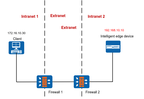
If the iClient S100 and HWT-IVS1800 are on different intranets, you need to configure NAT for the iClient S100 and HWT-IVS1800 respectively.
After NAT is configured for the iClient S100 and HWT-IVS1800, you can use the extranet HWT-IVS1800 IP address to log in to the iClient S100 to view live and recorded video and perform other service operations, as shown in Figure 5-55.
Data Plan
This section uses NAT mapping based on IP addresses and port translation as an example for data plan.
NAT based on IP address translation is relatively simple. In addition to IP address NAT on the firewall, the ports in the data plan need to be allowed in both directions. For details about how to allow ports, see the firewall documentation.
NE |
Require Configuration on the NE |
Pre-NAT IP Address |
Post-NAT IP Address |
Pre-NAT Port Number |
Post-NAT Port Number |
|---|---|---|---|---|---|
iClient S100 |
Yes |
172.16.10.30 |
10.10.10.30 |
58097 |
58097 |
Firewall 1 |
Yes (optional) You can either configure NAT or use routers and switches to implement the network connection between the iClient S100 and video and image management platform. |
172.16.10.30 |
10.10.10.30 |
58097 |
58097 |
Firewall 2 |
Yes |
192.168.10.10 |
10.10.10.10 |
|
|
Yes |
|
|
|
|
(Optional) Configuring NAT on Firewall 1
- Go to the firewall configuration page by referring to Logging In to the Firewall.
- Configure NAT based on the data plan.
- IP address NAT:
nat server name global Post-NAT IP address inside IP address of the computer running the client
- IP address and port NAT
- NAT of a single IP address and a single port
TCP: nat server name protocol tcp global Post-NAT IP address Post-NAT port number inside IP address Port number unr-route
UDP: nat server name protocol udp global Post-NAT IP address Post-NAT port number inside IP address Port number unr-route
- NAT of a single IP address and multiple ports
TCP: nat server name protocol tcp global Post-NAT IP address Post-NAT start port number Post-NAT end port number inside IP address Start port number End port number unr-route
UDP: nat server name protocol udp global Post-NAT IP address Post-NAT start port number Post-NAT end port number inside IP address Start port number End port number unr-route
- NAT of a single IP address and a single port
In the preceding commands, name indicates the unique name of the NAT server. The requirements on the server name are as follows:
- It is a string of 1 to 256 case-sensitive characters and can be a combination of digits.
- It must start with a letter or digit.
- It cannot be all, vsys, or all-systems and cannot be name, global, protocol, vpn-instance, zone, or their first several characters. For example, the value cannot be n, na, or nam.
- IP address NAT:
- Run the display current-configuration command to view the NAT configuration on the firewall and determine whether the NAT configuration is correct.
To modify the NAT configuration on the firewall, run the undo nat server name command to delete the original NAT configuration and then re-configure NAT.
- Configure a security policy on the firewall.
[FW] security-policy
[FW-policy-security] rule name rule_name
[FW-policy-security-rule-policy_sec1] source-zone untrust
[FW-policy-security-rule-policy_sec1] destination-zone trust
[FW-policy-security-rule-policy_sec1] destination-address video/image management platform IP address 32
[FW-policy-security-rule-policy_sec1] action permit
[FW-policy-security-rule-policy_sec1] quit
- rule_name: name of a security policy. You can configure multiple security policies as required.
- IP address of device in the Trust security zone: pre-NAT IP address of the intranet device. If there are multiple IP addresses, configure multiple security policies.
- Optional: Configure NAT ALG.Compared with the HWT-IVS1800+firewall NAT scheme, the firewall ALG scheme occupies fewer ports.
Configure port NAT.
By default, SIP port 5060 is used. However, GB/T 28181 uses SIP port 5080. Therefore, you need to perform this step.
[FW]acl 2000
[FW-acl-basic-2000]rule permit
[FW-acl-basic-2000]quit
[FW]port-mapping sip port 5080 acl 2000
[FW]quit
- Configure firewall NAT ALG to implement proper SIP packet forwarding.
[FW] firewall interzone trust untrust
[FW-interzone-trust-untrust] detect sip
[FW-interzone-trust-untrust] quit
- Verify that the settings have taken effect.
After the cameras are successfully registered, run the display firewall session table command on the firewall to view the session table. The following information indicates that the settings have taken effect:
Current Total Sessions : 2
sip VPN:public --> public X.X.X.X:2107-->10.10.10.10:5080[192.168.10.13:5080]
- Configure a static route to the extranet IP address (for example, 10.10.10.10) on the router, with the next hop being the intranet IP address of the firewall. In this manner, the messages returned from an extranet can be forwarded to the firewall.
In most cases, you need to contact the network administrator to configure the static route.
Configuring NAT on Firewall 2
- Go to the firewall configuration page by referring to Logging In to the Firewall.
- Configure NAT based on the data plan.
- IP address NAT:
nat server name global Post-NAT IP address inside IP address of HWT-IVS1800
- IP address and port NAT
- NAT of a single IP address and a single port
TCP: nat server name protocol tcp global Post-NAT IP address Post-NAT port number inside IP address Port number unr-route
UDP: nat server name protocol udp global Post-NAT IP address Post-NAT port number inside IP address Port number unr-route
- NAT of a single IP address and multiple ports
TCP: nat server name protocol tcp global Post-NAT IP address Post-NAT start port number Post-NAT end port number inside IP address Start port number End port number unr-route
UDP: nat server name protocol udp global Post-NAT IP address Post-NAT start port number Post-NAT end port number inside IP address Start port number End port number unr-route
- NAT of a single IP address and a single port
In the preceding commands, name indicates the unique name of the NAT server. The requirements on the server name are as follows:
- It is a string of 1 to 256 case-sensitive characters and can be a combination of digits.
- It must start with a letter or digit.
- It cannot be all, vsys, or all-systems and cannot be name, global, protocol, vpn-instance, zone, or their first several characters. For example, the value cannot be n, na, or nam.
- IP address NAT:
- Run the display current-configuration command to view the NAT configuration on the firewall and determine whether the NAT configuration is correct.
To modify the NAT configuration on the firewall, run the undo nat server name command to delete the original NAT configuration and then re-configure NAT.
- Configure a security policy on the firewall.
[FW] security-policy
[FW-policy-security] rule name rule_name
[FW-policy-security-rule-policy_sec1] source-zone untrust
[FW-policy-security-rule-policy_sec1] destination-zone trust
[FW-policy-security-rule-policy_sec1] destination-address video/image management platform IP address 32
[FW-policy-security-rule-policy_sec1] action permit
[FW-policy-security-rule-policy_sec1] quit
- rule_name: name of a security policy. You can configure multiple security policies as required.
- IP address of device in the Trust security zone: pre-NAT IP address of the intranet device. If there are multiple IP addresses, configure multiple security policies.
- Optional: Configure NAT ALG.Compared with the HWT-IVS1800+firewall NAT scheme, the firewall ALG scheme occupies fewer ports.
Configure port NAT.
By default, SIP port 5060 is used. However, GB/T 28181 uses SIP port 5080. Therefore, you need to perform this step.
[FW]acl 2000
[FW-acl-basic-2000]rule permit
[FW-acl-basic-2000]quit
[FW]port-mapping sip port 5080 acl 2000
[FW]quit
- Configure firewall NAT ALG to implement proper SIP packet forwarding.
[FW] firewall interzone trust untrust
[FW-interzone-trust-untrust] detect sip
[FW-interzone-trust-untrust] quit
- Verify that the settings have taken effect.
After the cameras are successfully registered, run the display firewall session table command on the firewall to view the session table. The following information indicates that the settings have taken effect:
Current Total Sessions : 2
sip VPN:public --> public X.X.X.X:2107-->10.10.10.10:5080[192.168.10.13:5080]
- Configure a static route to the extranet IP address (for example, 10.10.10.90) on the router, with the next hop being the intranet IP address of the firewall. In this manner, the messages returned from an extranet can be forwarded to the firewall.
In most cases, you need to contact the network administrator to configure the static route.
Configuring NAT on the HWT-IVS1800
- Log in to the OMU portal as the admin user. ( Logging In to the OMU portal)
- Choose System > Advanced Configuration.
- Configure NAT information, as shown in Figure 5-56.
The parameters to be set vary depending on the scenario where the iClient S100 is connected to the HWT-IVS1800.
- If the HWT-IVS1800 deployed in single- or dual-address mode is connected to the iClient S100 only through the northbound interface, set the parameters described in Table 5-34.
Table 5-34 Parameter description
Module
Parameter
Description
PUBLIC
NNatIP
Northbound IP address of the HWT-IVS1800, which must be the same as the post-NAT IP address configured on the firewall.
NatRtspServerPort
Post-NAT northbound port number of the MU of the HWT-IVS1800, which must be the same as the post-NAT port number configured on the firewall. The default port number is 554.
- If the HWT-IVS1800 deployed in dual-address mode is connected to the iClient S100 only through the southbound interface, set the parameters described in Table 5-35.
Table 5-35 Parameter description
Module
Parameter
Description
PUBLIC
SNatIP
Southbound IP address of the HWT-IVS1800, which must be the same as the post-NAT IP address configured on the firewall.
NatSRtspPort
Post-NAT southbound port number of the MU of the HWT-IVS1800, which must be the same as the post-NAT port number configured on the firewall. The default port number is 554.
- If the HWT-IVS1800 deployed in dual-address mode is connected to the iClient S100 through both the southbound and northbound interfaces, set the parameters described in Table 5-34 and Table 5-35.
- If the HWT-IVS1800 deployed in single- or dual-address mode is connected to the iClient S100 only through the northbound interface, set the parameters described in Table 5-34.
- Log in to the iClient S100 again and add HWT-IVS1800 devices.
When adding a device, use the HWT-IVS1800 IP address and port number translated on the firewall.
NAT Network Between the HWT-IVS1800 and the Upper-Level Video and Image Management Platform
Upper-Level Video and Image Management Platform on an Extranet and HWT-IVS1800 on an Intranet
Context
Network
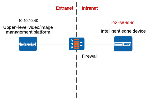
If the upper-level video and image management platform is on an extranet and the HWT-IVS1800 is on an intranet, the HWT-IVS1800 cannot be registered with the upper-level video and image management platform. To solve this problem, you can configure NAT by translating the IP address and port number of the HWT-IVS1800 to those on an extranet, as shown in Figure 5-57.
Protocols That Support NAT
Registration Type |
Protocol |
Support NAT |
Procedure |
|---|---|---|---|
Passive registration |
ONVIF |
Yes |
|
RESTful |
Yes |
||
Proactive registration |
GB/T 28181 |
Yes |
ONVIF
Data Plan
This section uses NAT mapping based on IP addresses and port translation as an example for data plan.
NAT based on IP address translation is relatively simple. In addition to IP address NAT on the firewall, the ports in the data plan need to be allowed in both directions. For details about how to allow ports, see the firewall documentation.
NE |
Require Configuration on the NE |
Pre-NAT IP Address |
Post-NAT IP Address |
Pre-NAT Port Number |
Post-NAT Port Number |
|---|---|---|---|---|---|
Upper-level video and image management platform |
No |
- |
- |
- |
- |
Firewall |
Yes |
192.168.10.10 |
10.10.10.10 |
|
|
Yes |
|
|
|
NOTE:
|
Configuring NAT on the Firewall
- Go to the firewall configuration page by referring to Logging In to the Firewall.
- Configure NAT based on the data plan.
- IP address NAT:
nat server name global Post-NAT IP address inside IP address of HWT-IVS1800
- IP address and port NAT
- NAT of a single IP address and a single port
TCP: nat server name protocol tcp global Post-NAT IP address Post-NAT port number inside IP address Port number unr-route
UDP: nat server name protocol udp global Post-NAT IP address Post-NAT port number inside IP address Port number unr-route
- NAT of a single IP address and multiple ports
TCP: nat server name protocol tcp global Post-NAT IP address Post-NAT start port number Post-NAT end port number inside IP address Start port number End port number unr-route
UDP: nat server name protocol udp global Post-NAT IP address Post-NAT start port number Post-NAT end port number inside IP address Start port number End port number unr-route
- NAT of a single IP address and a single port
In the preceding commands, name indicates the unique name of the NAT server. The requirements on the server name are as follows:
- It is a string of 1 to 256 case-sensitive characters and can be a combination of digits.
- It must start with a letter or digit.
- It cannot be all, vsys, or all-systems and cannot be name, global, protocol, vpn-instance, zone, or their first several characters. For example, the value cannot be n, na, or nam.
- IP address NAT:
- Run the display current-configuration command to view the NAT configuration on the firewall and determine whether the NAT configuration is correct.
To modify the NAT configuration on the firewall, run the undo nat server name command to delete the original NAT configuration and then re-configure NAT.
- Configure a security policy on the firewall.
[FW] security-policy
[FW-policy-security] rule name rule_name
[FW-policy-security-rule-policy_sec1] source-zone untrust
[FW-policy-security-rule-policy_sec1] destination-zone trust
[FW-policy-security-rule-policy_sec1] destination-address video/image management platform IP address 32
[FW-policy-security-rule-policy_sec1] action permit
[FW-policy-security-rule-policy_sec1] quit
- rule_name: name of a security policy. You can configure multiple security policies as required.
- IP address of device in the Trust security zone: pre-NAT IP address of the intranet device. If there are multiple IP addresses, configure multiple security policies.
- Optional: Configure NAT ALG.Compared with the HWT-IVS1800+firewall NAT scheme, the firewall ALG scheme occupies fewer ports.
Configure port NAT.
By default, SIP port 5060 is used. However, GB/T 28181 uses SIP port 5080. Therefore, you need to perform this step.
[FW]acl 2000
[FW-acl-basic-2000]rule permit
[FW-acl-basic-2000]quit
[FW]port-mapping sip port 5080 acl 2000
[FW]quit
- Configure firewall NAT ALG to implement proper SIP packet forwarding.
[FW] firewall interzone trust untrust
[FW-interzone-trust-untrust] detect sip
[FW-interzone-trust-untrust] quit
- Verify that the settings have taken effect.
After the cameras are successfully registered, run the display firewall session table command on the firewall to view the session table. The following information indicates that the settings have taken effect:
Current Total Sessions : 2
sip VPN:public --> public X.X.X.X:2107-->10.10.10.10:5080[192.168.10.13:5080]
- Configure a static route to the extranet IP address (for example, 10.10.10.90) on the router, with the next hop being the intranet IP address of the firewall. In this manner, the messages returned from an extranet can be forwarded to the firewall.
In most cases, you need to contact the network administrator to configure the static route.
Configuring NAT on the HWT-IVS1800
- Log in to the OMU portal as the admin user. ( Logging In to the OMU portal)
- Choose System > Advanced Configuration.
- Configure NAT information, as shown in Figure 5-58.
The parameters to be set vary depending on the scenario where the HWT-IVS1800 is connected to the upper-level video and image management platform.
- If the HWT-IVS1800 deployed in single- or dual-address mode is connected to the upper-level video and image management platform only through the northbound interface, set the parameters described in Table 5-38.
Table 5-38 Parameter description
Module
Parameter
Description
PUBLIC
OCG_NAT_LIST
List of subnets, which is used by the HWT-IVS1800 to determine whether NAT needs to be configured for IP addresses of northbound devices.
- If no user-defined NAT subnet list is configured, the system performs NAT for all IP addresses except standard subnet addresses by default.The standard private network IP address ranges are as follows:
Class A: 10.0.0.1 to 10.255.255.254
Class B: 172.16.0.1 to 172.31.255.254
Class C: 192.168.0.1 to 192.168.255.254
- If a user-defined NAT subnet list is configured, the system performs NAT for all IP addresses (including standard private IP addresses) except those in the NAT subnet list.
If there are multiple IP subnets, use semicolons (;) to separate them, for example, 192.168.1.0/24;192.168.2.0/24.
NNatIP
Northbound IP address of the HWT-IVS1800, which must be the same as the post-NAT IP address configured on the firewall.
NatRtspServerPort
Post-NAT northbound port number of the MU of the HWT-IVS1800, which must be the same as the post-NAT port number configured on the firewall. The default port number is 554.
OCGListeningAdapter
Select eth1.
This parameter is involved only in dual-address mode. By default, this parameter is not involved in single-address mode.
- If no user-defined NAT subnet list is configured, the system performs NAT for all IP addresses except standard subnet addresses by default.
- If the HWT-IVS1800 deployed in dual-address mode is connected to the upper-level video and image management platform only through the southbound interface, set the parameters described in Table 5-39.
In dual-address mode, the HWT-IVS1800 cannot be connected to the upper-level video and image management platform through the southbound and northbound interfaces simultaneously.
Table 5-39 Parameter descriptionModule
Parameter
Description
PUBLIC
OCG_NAT_LIST
List of subnets, which is used by the HWT-IVS1800 to determine whether NAT needs to be configured for IP addresses of northbound devices.
- If no user-defined NAT subnet list is configured, the system performs NAT for all IP addresses except standard subnet addresses by default.The standard private network IP address ranges are as follows:
Class A: 10.0.0.1 to 10.255.255.254
Class B: 172.16.0.1 to 172.31.255.254
Class C: 192.168.0.1 to 192.168.255.254
- If a user-defined NAT subnet list is configured, the system performs NAT for all IP addresses (including standard private IP addresses) except those in the NAT subnet list.
If there are multiple IP subnets, use semicolons (;) to separate them, for example, 192.168.1.0/24;192.168.2.0/24.
SNatIP
Southbound IP address of the HWT-IVS1800, which must be the same as the post-NAT IP address configured on the firewall.
NatSRtspPort
Post-NAT southbound port number of the MU of the HWT-IVS1800, which must be the same as the post-NAT port number configured on the firewall. The default port number is 554.
OCGListeningAdapter
Select eth0.
- If no user-defined NAT subnet list is configured, the system performs NAT for all IP addresses except standard subnet addresses by default.
- If the HWT-IVS1800 deployed in single- or dual-address mode is connected to the upper-level video and image management platform only through the northbound interface, set the parameters described in Table 5-38.
RESTful
Data Plan
This section uses NAT mapping based on IP addresses and port translation as an example for data plan.
NAT based on IP address translation is relatively simple. In addition to IP address NAT on the firewall, the ports in the data plan need to be allowed in both directions. For details about how to allow ports, see the firewall documentation.
NE |
Require Configuration on the NE |
Pre-NAT IP Address |
Post-NAT IP Address |
Pre-NAT Port Number |
Post-NAT Port Number |
|---|---|---|---|---|---|
Upper-level video and image management platform |
No |
- |
- |
- |
- |
Firewall |
Yes |
192.168.10.10 |
10.10.10.10 |
|
NOTE:
|
HWT-IVS1800 |
Yes |
|
|
|
NOTE:
|
Configuring NAT on the Firewall
- Go to the firewall configuration page by referring to Logging In to the Firewall.
- Configure NAT based on the data plan.
- IP address NAT:
nat server name global Post-NAT IP address inside IP address of HWT-IVS1800
- IP address and port NAT
- NAT of a single IP address and a single port
TCP: nat server name protocol tcp global Post-NAT IP address Post-NAT port number inside IP address Port number unr-route
UDP: nat server name protocol udp global Post-NAT IP address Post-NAT port number inside IP address Port number unr-route
- NAT of a single IP address and multiple ports
TCP: nat server name protocol tcp global Post-NAT IP address Post-NAT start port number Post-NAT end port number inside IP address Start port number End port number unr-route
UDP: nat server name protocol udp global Post-NAT IP address Post-NAT start port number Post-NAT end port number inside IP address Start port number End port number unr-route
- NAT of a single IP address and a single port
In the preceding commands, name indicates the unique name of the NAT server. The requirements on the server name are as follows:
- It is a string of 1 to 256 case-sensitive characters and can be a combination of digits.
- It must start with a letter or digit.
- It cannot be all, vsys, or all-systems and cannot be name, global, protocol, vpn-instance, zone, or their first several characters. For example, the value cannot be n, na, or nam.
- IP address NAT:
- Run the display current-configuration command to view the NAT configuration on the firewall and determine whether the NAT configuration is correct.
To modify the NAT configuration on the firewall, run the undo nat server name command to delete the original NAT configuration and then re-configure NAT.
- Configure a security policy on the firewall.
[FW] security-policy
[FW-policy-security] rule name rule_name
[FW-policy-security-rule-policy_sec1] source-zone untrust
[FW-policy-security-rule-policy_sec1] destination-zone trust
[FW-policy-security-rule-policy_sec1] destination-address video/image management platform IP address 32
[FW-policy-security-rule-policy_sec1] action permit
[FW-policy-security-rule-policy_sec1] quit
- rule_name: name of a security policy. You can configure multiple security policies as required.
- IP address of device in the Trust security zone: pre-NAT IP address of the intranet device. If there are multiple IP addresses, configure multiple security policies.
- Optional: Configure NAT ALG.Compared with the HWT-IVS1800+firewall NAT scheme, the firewall ALG scheme occupies fewer ports.
Configure port NAT.
By default, SIP port 5060 is used. However, GB/T 28181 uses SIP port 5080. Therefore, you need to perform this step.
[FW]acl 2000
[FW-acl-basic-2000]rule permit
[FW-acl-basic-2000]quit
[FW]port-mapping sip port 5080 acl 2000
[FW]quit
- Configure firewall NAT ALG to implement proper SIP packet forwarding.
[FW] firewall interzone trust untrust
[FW-interzone-trust-untrust] detect sip
[FW-interzone-trust-untrust] quit
- Verify that the settings have taken effect.
After the cameras are successfully registered, run the display firewall session table command on the firewall to view the session table. The following information indicates that the settings have taken effect:
Current Total Sessions : 2
sip VPN:public --> public X.X.X.X:2107-->10.10.10.10:5080[192.168.10.13:5080]
- Configure a static route to the extranet IP address (for example, 10.10.10.90) on the router, with the next hop being the intranet IP address of the firewall. In this manner, the messages returned from an extranet can be forwarded to the firewall.
In most cases, you need to contact the network administrator to configure the static route.
Configuring NAT on the HWT-IVS1800
- Log in to the OMU portal as the admin user. ( Logging In to the OMU portal)
- Choose System > Advanced Configuration.
- Configure NAT information, as shown in Figure 5-59.
The parameters to be set vary depending on the scenario where the HWT-IVS1800 is connected to the upper-level video and image management platform.
- If the HWT-IVS1800 deployed in single- or dual- address mode is connected to the upper-level video and image management platform only through the northbound interface, set the parameters described in Table 5-41.
Table 5-41 Parameter description
Module
Parameter
Description
PUBLIC
NNatIP
Northbound IP address of the HWT-IVS1800, which must be the same as the post-NAT IP address configured on the firewall.
NatRtspServerPort
Post-NAT northbound port number of the MU of the HWT-IVS1800, which must be the same as the post-NAT port number configured on the firewall.
- If the HWT-IVS1800 deployed in dual-address mode is connected to the upper-level video and image management platform only through the southbound interface, set the parameters described in Table 5-42.
In dual-address mode, the HWT-IVS1800 cannot be connected to the upper-level video and image management platform through the southbound and northbound interfaces simultaneously.
Table 5-42 Parameter descriptionModule
Parameter
Description
PUBLIC
SNatIP
Southbound IP address of the HWT-IVS1800, which must be the same as the post-NAT IP address configured on the firewall.
NatSRtspPort
Post-NAT southbound port number of the MU of the HWT-IVS1800, which must be the same as the post-NAT port number configured on the firewall.
- If the HWT-IVS1800 deployed in single- or dual- address mode is connected to the upper-level video and image management platform only through the northbound interface, set the parameters described in Table 5-41.
GB/T 28181
Dynamic NAT
Application Scenario
The HWT-IVS1800 on an intranet is connected to the upper-level video and image management platform on an extranet (without fixed IP addresses) through GB/T 28181.
Assume that the HWT-IVS1800 on an intranet is connected to the video and image management platform on the Internet through a router (with the LAN port of the router connected to the HWT-IVS1800 and the WAN port of the router connected to the Internet), and the IP address of the WAN port is dynamically allocated by the carrier. In this scenario, the router will dynamically translate the source IP address (IP address of the LAN port) into the IP address of the WAN port.
Data Plan
NE |
Require Configuration on the NE |
Pre-NAT IP Address |
Post-NAT IP Address |
Pre-NAT Port Number |
Post-NAT Port Number |
|---|---|---|---|---|---|
Upper-level video and image management platform |
No |
- |
- |
- |
- |
Firewall |
Yes |
192.168.10.10 |
- |
|
Dynamically generated by the router or firewall. |
HWT-IVS1800 |
Yes |
|
- |
|
- |
Configuring NAT on the HWT-IVS1800
- Log in to the OMU portal as the admin user. ( Logging In to the OMU portal)
- Choose System > Advanced Configuration.
- Configure NAT information, as shown in Figure 5-60.
Table 5-44 describes the parameters.
Static NAT
Prerequisites
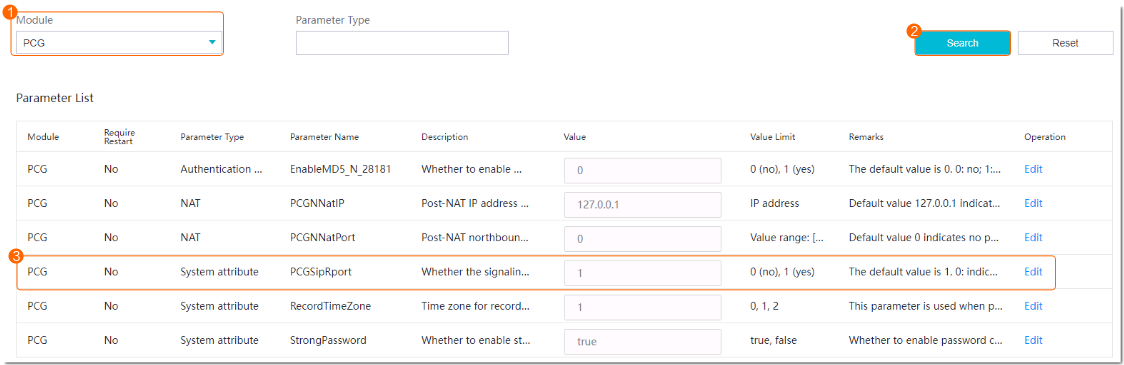
You have set PCGSipRport to 1 by referring to Configuring NAT on the HWT-IVS1800.
Data Plan
This section uses NAT mapping based on IP addresses and port translation as an example for data plan.
NAT based on IP address translation is relatively simple. In addition to IP address NAT on the firewall, the ports in the data plan need to be allowed in both directions. For details about how to allow ports, see the firewall documentation.
NE |
Require Configuration on the NE |
Pre-NAT IP Address |
Post-NAT IP Address |
Pre-NAT Port Number |
Post-NAT Port Number |
|---|---|---|---|---|---|
Upper-level video and image management platform |
No |
- |
- |
- |
- |
Firewall |
Yes |
192.168.10.10 |
10.10.10.10 |
|
NOTE:
|
HWT-IVS1800 |
Yes |
|
|
|
NOTE:
|
Configuring NAT on the Firewall
- Go to the firewall configuration page by referring to Logging In to the Firewall.
- Configure NAT based on the data plan.
- IP address NAT:
nat server name global Post-NAT IP address inside IP address of HWT-IVS1800
- IP address and port NAT
- NAT of a single IP address and a single port
TCP: nat server name protocol tcp global Post-NAT IP address Post-NAT port number inside IP address Port number unr-route
UDP: nat server name protocol udp global Post-NAT IP address Post-NAT port number inside IP address Port number unr-route
- NAT of a single IP address and multiple ports
TCP: nat server name protocol tcp global Post-NAT IP address Post-NAT start port number Post-NAT end port number inside IP address Start port number End port number unr-route
UDP: nat server name protocol udp global Post-NAT IP address Post-NAT start port number Post-NAT end port number inside IP address Start port number End port number unr-route
- NAT of a single IP address and a single port
In the preceding commands, name indicates the unique name of the NAT server. The requirements on the server name are as follows:
- It is a string of 1 to 256 case-sensitive characters and can be a combination of digits.
- It must start with a letter or digit.
- It cannot be all, vsys, or all-systems and cannot be name, global, protocol, vpn-instance, zone, or their first several characters. For example, the value cannot be n, na, or nam.
- IP address NAT:
- Run the display current-configuration command to view the NAT configuration on the firewall and determine whether the NAT configuration is correct.
To modify the NAT configuration on the firewall, run the undo nat server name command to delete the original NAT configuration and then re-configure NAT.
- Configure a security policy on the firewall.
[FW] security-policy
[FW-policy-security] rule name rule_name
[FW-policy-security-rule-policy_sec1] source-zone untrust
[FW-policy-security-rule-policy_sec1] destination-zone trust
[FW-policy-security-rule-policy_sec1] destination-address video/image management platform IP address 32
[FW-policy-security-rule-policy_sec1] action permit
[FW-policy-security-rule-policy_sec1] quit
- rule_name: name of a security policy. You can configure multiple security policies as required.
- IP address of device in the Trust security zone: pre-NAT IP address of the intranet device. If there are multiple IP addresses, configure multiple security policies.
- Optional: Configure NAT ALG.Compared with the HWT-IVS1800+firewall NAT scheme, the firewall ALG scheme occupies fewer ports.
Configure port NAT.
By default, SIP port 5060 is used. However, GB/T 28181 uses SIP port 5080. Therefore, you need to perform this step.
[FW]acl 2000
[FW-acl-basic-2000]rule permit
[FW-acl-basic-2000]quit
[FW]port-mapping sip port 5080 acl 2000
[FW]quit
- Configure firewall NAT ALG to implement proper SIP packet forwarding.
[FW] firewall interzone trust untrust
[FW-interzone-trust-untrust] detect sip
[FW-interzone-trust-untrust] quit
- Verify that the settings have taken effect.
After the cameras are successfully registered, run the display firewall session table command on the firewall to view the session table. The following information indicates that the settings have taken effect:
Current Total Sessions : 2
sip VPN:public --> public X.X.X.X:2107-->10.10.10.10:5080[192.168.10.13:5080]
- Configure a static route to the extranet IP address (for example, 10.10.10.90) on the router, with the next hop being the intranet IP address of the firewall. In this manner, the messages returned from an extranet can be forwarded to the firewall.
In most cases, you need to contact the network administrator to configure the static route.
Configuring NAT on the HWT-IVS1800
- Log in to the OMU portal as the admin user. ( Logging In to the OMU portal)
- Choose System > Advanced Configuration.
- Configure NAT information, as shown in Figure 5-61.
The parameters to be set vary depending on the scenario where the HWT-IVS1800 is connected to the upper-level video and image management platform.
- If the HWT-IVS1800 deployed in single- or dual- address mode is connected to the upper-level video and image management platform only through the northbound interface, set the parameters described in Table 5-46.
Table 5-46 Parameter description
Module
Parameter
Description
MU
TcpSendMediaPort
Start TCP port number of the MU of the HWT-IVS1800. After the setting, the system automatically occupies the port number specified by this parameter and the following 65 port numbers.
The value range is [10000,30000], and [n,n+65] cannot contain port 18531. The value n indicates the start port number.
UdpSendMediaPort
Start UDP port number of the MU of the HWT-IVS1800. After the setting, the system automatically occupies the port number specified by this parameter and the following 519 port numbers.
The value range is [10000,30000], and [n,n+519] cannot contain port 18531. The value n indicates the start port number.
PUBLIC
NNatIP
Northbound IP address of the HWT-IVS1800, which must be the same as the post-NAT IP address configured on the firewall.
PCGNNatPort
Post-NAT port number of the PCG of the HWT-IVS1800, which must be the same as the post-NAT port number configured on the firewall. The default port number is 5061.
- If the HWT-IVS1800 deployed in dual-address mode is connected to the upper-level video and image management platform only through the southbound interface, set the parameters described in Table 5-47.
In dual-address mode, the HWT-IVS1800 cannot be connected to the upper-level video and image management platform through the southbound and northbound interfaces simultaneously.
Table 5-47 Parameter descriptionModule
Parameter
Description
MU
TcpSendMediaPort
Start TCP port number of the MU of the HWT-IVS1800. After the setting, the system automatically occupies the port number specified by this parameter and the following 65 port numbers.
The value range is [10000,30000], and [n,n+65] cannot contain port 18531. The value n indicates the start port number.
UdpSendMediaPort
Start UDP port number of the MU of the HWT-IVS1800. After the setting, the system automatically occupies the port number specified by this parameter and the following 519 port numbers.
The value range is [10000,30000], and [n,n+519] cannot contain port 18531. The value n indicates the start port number.
PUBLIC
SNatIP
Southbound IP address of the HWT-IVS1800, which must be the same as the post-NAT IP address configured on the firewall.
PCGNNatPort
Post-NAT southbound port number of the PCG of the HWT-IVS1800, which must be the same as the post-NAT port number configured on the firewall. The default port number is 5061.
PCGListeningAdapter
Network adapter for listening on the GB/T 28181 service of the HWT-IVS1800, which must be set to the southbound network adapter eth0.
- If the HWT-IVS1800 deployed in single- or dual- address mode is connected to the upper-level video and image management platform only through the northbound interface, set the parameters described in Table 5-46.
Upper-Level Video and Image Management Platform on an Intranet and HWT-IVS1800 on an Extranet
Context
Network
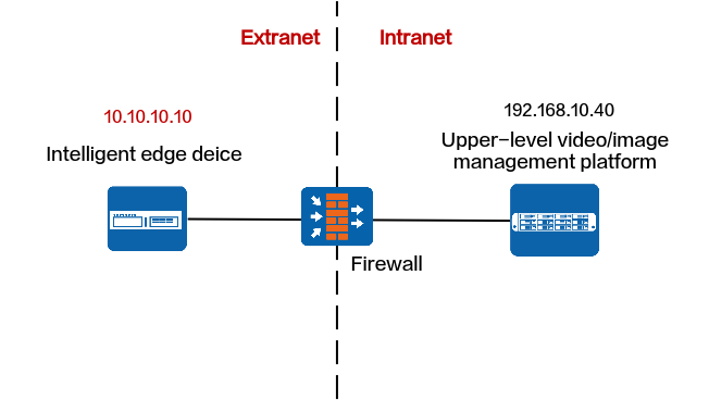
If the upper-level video and image management platform is on an intranet and the HWT-IVS1800 is on an extranet, the HWT-IVS1800 cannot be directly registered with the upper-level video and image management platform. To solve this problem, you need to configure NAT for the upper-level video and image management platform by translating the IP address and port number of the upper-level video and image management platform to those on the extranet, as shown in Figure 5-62.
Protocols That Support NAT
Registration Type |
Protocol |
Support NAT |
Procedure |
|---|---|---|---|
Passive registration |
ONVIF |
No |
- |
RESTful |
Yes |
||
Proactive registration |
GB/T 28181 |
Yes |
RESTful
Data Plan
NE |
Require Configuration on the NE |
Pre-NAT IP Address |
Post-NAT IP Address |
Pre-NAT Port Number |
Post-NAT Port Number |
|---|---|---|---|---|---|
Upper-level video and image management platform |
Yes |
For details, see the product documentation of the upper-level video and image management platform. |
|||
Firewall |
Yes |
For details, see the product documentation of the upper-level video and image management platform. |
|||
HWT-IVS1800 |
No |
- |
- |
- |
- |
GB/T 28181
Data Plan
NE |
Require Configuration on the NE |
Pre-NAT IP Address |
Post-NAT IP Address |
Pre-NAT Port Number |
Post-NAT Port Number |
|---|---|---|---|---|---|
Upper-level video and image management platform |
Yes |
For details, see the product documentation of the upper-level video and image management platform. |
|||
Firewall |
Yes |
For details, see the product documentation of the upper-level video and image management platform. |
|||
HWT-IVS1800 |
No |
- |
- |
- |
- |
Upper-Level Video and Image Management Platform and HWT-IVS1800 on Different Intranets
Context
Network
If the upper-level video and image management platform and HWT-IVS1800 are on different intranets, the HWT-IVS1800 cannot be directly registered with the upper-level video and image management platform. To solve this problem, you need to configure NAT for the upper-level video and image management platform and HWT-IVS1800 by translating their IP addresses and port numbers to those on the extranet, as shown in Figure 5-63.
Protocols That Support NAT
Registration Type |
Protocol |
Support NAT |
Procedure |
|---|---|---|---|
Passive registration |
ONVIF |
No |
- |
RESTful |
Yes |
||
Proactive registration |
GB/T 28181 |
Yes |
RESTful
Data Plan
This section uses NAT mapping based on IP addresses and port translation as an example for data plan.
NAT based on IP address translation is relatively simple. In addition to IP address NAT on the firewall, the ports in the data plan need to be allowed in both directions. For details about how to allow ports, see the firewall documentation.
NE |
Require Configuration on the NE |
Pre-NAT IP Address |
Post-NAT IP Address |
Pre-NAT Port Number |
Post-NAT Port Number |
|---|---|---|---|---|---|
Upper-level video and image management platform |
Yes |
For details, see the product documentation of the upper-level video and image management platform. |
|||
Firewall 1 |
Yes |
For details, see the product documentation of the upper-level video and image management platform. |
|||
Firewall 2 |
Yes |
192.168.10.10 |
10.10.10.10 |
|
NOTE:
|
HWT-IVS1800 |
Yes |
|
|
|
NOTE:
|
Configuring NAT on Firewall 2
- Go to the firewall configuration page by referring to Logging In to the Firewall.
- Configure NAT based on the data plan.
- IP address NAT:
nat server name global Post-NAT IP address inside IP address of HWT-IVS1800
- IP address and port NAT
- NAT of a single IP address and a single port
TCP: nat server name protocol tcp global Post-NAT IP address Post-NAT port number inside IP address Port number unr-route
UDP: nat server name protocol udp global Post-NAT IP address Post-NAT port number inside IP address Port number unr-route
- NAT of a single IP address and multiple ports
TCP: nat server name protocol tcp global Post-NAT IP address Post-NAT start port number Post-NAT end port number inside IP address Start port number End port number unr-route
UDP: nat server name protocol udp global Post-NAT IP address Post-NAT start port number Post-NAT end port number inside IP address Start port number End port number unr-route
- NAT of a single IP address and a single port
In the preceding commands, name indicates the unique name of the NAT server. The requirements on the server name are as follows:
- It is a string of 1 to 256 case-sensitive characters and can be a combination of digits.
- It must start with a letter or digit.
- It cannot be all, vsys, or all-systems and cannot be name, global, protocol, vpn-instance, zone, or their first several characters. For example, the value cannot be n, na, or nam.
- IP address NAT:
- Run the display current-configuration command to view the NAT configuration on the firewall and determine whether the NAT configuration is correct.
To modify the NAT configuration on the firewall, run the undo nat server name command to delete the original NAT configuration and then re-configure NAT.
- Configure a security policy on the firewall.
[FW] security-policy
[FW-policy-security] rule name rule_name
[FW-policy-security-rule-policy_sec1] source-zone untrust
[FW-policy-security-rule-policy_sec1] destination-zone trust
[FW-policy-security-rule-policy_sec1] destination-address video/image management platform IP address 32
[FW-policy-security-rule-policy_sec1] action permit
[FW-policy-security-rule-policy_sec1] quit
- rule_name: name of a security policy. You can configure multiple security policies as required.
- IP address of device in the Trust security zone: pre-NAT IP address of the intranet device. If there are multiple IP addresses, configure multiple security policies.
- Optional: Configure NAT ALG.Compared with the HWT-IVS1800+firewall NAT scheme, the firewall ALG scheme occupies fewer ports.
Configure port NAT.
By default, SIP port 5060 is used. However, GB/T 28181 uses SIP port 5080. Therefore, you need to perform this step.
[FW]acl 2000
[FW-acl-basic-2000]rule permit
[FW-acl-basic-2000]quit
[FW]port-mapping sip port 5080 acl 2000
[FW]quit
- Configure firewall NAT ALG to implement proper SIP packet forwarding.
[FW] firewall interzone trust untrust
[FW-interzone-trust-untrust] detect sip
[FW-interzone-trust-untrust] quit
- Verify that the settings have taken effect.
After the cameras are successfully registered, run the display firewall session table command on the firewall to view the session table. The following information indicates that the settings have taken effect:
Current Total Sessions : 2
sip VPN:public --> public X.X.X.X:2107-->10.10.10.10:5080[192.168.10.13:5080]
- Configure a static route to the extranet IP address (for example, 10.10.10.90) on the router, with the next hop being the intranet IP address of the firewall. In this manner, the messages returned from an extranet can be forwarded to the firewall.
In most cases, you need to contact the network administrator to configure the static route.
Configuring NAT on the HWT-IVS1800
- Log in to the OMU portal as the admin user. ( Logging In to the OMU portal)
- Choose System > Advanced Configuration.
- Configure NAT information, as shown in Figure 5-64.
The parameters to be set vary depending on the scenario where the HWT-IVS1800 is connected to the upper-level video and image management platform.
- If the HWT-IVS1800 deployed in single- or dual- address mode is connected to the upper-level video and image management platform only through the northbound interface, set the parameters described in Table 5-53.
Table 5-53 Parameter description
Module
Parameter
Description
PUBLIC
NNatIP
Northbound IP address of the HWT-IVS1800, which must be the same as the post-NAT IP address configured on the firewall.
NatRtspServerPort
Post-NAT northbound port number of the MU of the HWT-IVS1800, which must be the same as the post-NAT port number configured on the firewall.
- If the HWT-IVS1800 deployed in dual-address mode is connected to the upper-level video and image management platform only through the southbound interface, set the parameters described in Table 5-54.
In dual-address mode, the HWT-IVS1800 cannot be connected to the upper-level video and image management platform through the southbound and northbound interfaces simultaneously.
Table 5-54 Parameter descriptionModule
Parameter
Description
PUBLIC
SNatIP
Southbound IP address of the HWT-IVS1800, which must be the same as the post-NAT IP address configured on the firewall.
NatSRtspPort
Post-NAT southbound port number of the MU of the HWT-IVS1800, which must be the same as the post-NAT port number configured on the firewall.
- If the HWT-IVS1800 deployed in single- or dual- address mode is connected to the upper-level video and image management platform only through the northbound interface, set the parameters described in Table 5-53.
GB/T 28181
Dynamic NAT
Application Scenario
The HWT-IVS1800 on an intranet is connected to the upper-level video and image management platform on an extranet (without fixed IP addresses) through GB/T 28181.
Assume that the HWT-IVS1800 on an intranet is connected to the video and image management platform on the Internet through a router (with the LAN port of the router connected to the HWT-IVS1800 and the WAN port of the router connected to the Internet), and the IP address of the WAN port is dynamically allocated by the carrier. In this scenario, the router will dynamically translate the source IP address (IP address of the LAN port) into the IP address of the WAN port.
Data Plan
NE |
Require Configuration on the NE |
Pre-NAT IP Address |
Post-NAT IP Address |
Pre-NAT Port Number |
Post-NAT Port Number |
|---|---|---|---|---|---|
Upper-level video and image management platform |
Yes |
For details, see the product documentation of the upper-level video and image management platform. |
|||
Firewall 1 |
Yes |
For details, see the product documentation of the upper-level video and image management platform. |
|||
Firewall 2 |
Yes |
192.168.10.10 |
- |
|
Dynamically generated by the router or firewall. |
HWT-IVS1800 |
Yes |
|
- |
|
- |
Configuring NAT on the HWT-IVS1800
- Log in to the OMU portal as the admin user. ( Logging In to the OMU portal)
- Choose System > Advanced Configuration.
- Configure NAT information, as shown in Figure 5-65.
Table 5-56 describes the parameters.
Static NAT
Prerequisites
You have set PCGSipRport to 1 by referring to Configuring NAT on the HWT-IVS1800.
Data Plan
This section uses NAT mapping based on IP addresses and port translation as an example for data plan.
NAT based on IP address translation is relatively simple. In addition to IP address NAT on the firewall, the ports in the data plan need to be allowed in both directions. For details about how to allow ports, see the firewall documentation.
NE |
Require Configuration on the NE |
Pre-NAT IP Address |
Post-NAT IP Address |
Pre-NAT Port Number |
Post-NAT Port Number |
|---|---|---|---|---|---|
Upper-level video and image management platform |
Yes |
For details, see the product documentation of the upper-level video and image management platform. |
|||
Firewall 1 |
Yes |
For details, see the product documentation of the upper-level video and image management platform. |
|||
Firewall 2 |
Yes |
192.168.10.10 |
10.10.10.10 |
|
NOTE:
|
HWT-IVS1800 |
Yes |
|
|
|
NOTE:
|
Configuring NAT on Firewall 2
- Go to the firewall configuration page by referring to Logging In to the Firewall.
- Configure NAT based on the data plan.
- IP address NAT:
nat server name global Post-NAT IP address inside IP address of HWT-IVS1800
- IP address and port NAT
- NAT of a single IP address and a single port
TCP: nat server name protocol tcp global Post-NAT IP address Post-NAT port number inside IP address Port number unr-route
UDP: nat server name protocol udp global Post-NAT IP address Post-NAT port number inside IP address Port number unr-route
- NAT of a single IP address and multiple ports
TCP: nat server name protocol tcp global Post-NAT IP address Post-NAT start port number Post-NAT end port number inside IP address Start port number End port number unr-route
UDP: nat server name protocol udp global Post-NAT IP address Post-NAT start port number Post-NAT end port number inside IP address Start port number End port number unr-route
- NAT of a single IP address and a single port
In the preceding commands, name indicates the unique name of the NAT server. The requirements on the server name are as follows:
- It is a string of 1 to 256 case-sensitive characters and can be a combination of digits.
- It must start with a letter or digit.
- It cannot be all, vsys, or all-systems and cannot be name, global, protocol, vpn-instance, zone, or their first several characters. For example, the value cannot be n, na, or nam.
- IP address NAT:
- Run the display current-configuration command to view the NAT configuration on the firewall and determine whether the NAT configuration is correct.
To modify the NAT configuration on the firewall, run the undo nat server name command to delete the original NAT configuration and then re-configure NAT.
- Configure a security policy on the firewall.
[FW] security-policy
[FW-policy-security] rule name rule_name
[FW-policy-security-rule-policy_sec1] source-zone untrust
[FW-policy-security-rule-policy_sec1] destination-zone trust
[FW-policy-security-rule-policy_sec1] destination-address video/image management platform IP address 32
[FW-policy-security-rule-policy_sec1] action permit
[FW-policy-security-rule-policy_sec1] quit
- rule_name: name of a security policy. You can configure multiple security policies as required.
- IP address of device in the Trust security zone: pre-NAT IP address of the intranet device. If there are multiple IP addresses, configure multiple security policies.
- Optional: Configure NAT ALG.Compared with the HWT-IVS1800+firewall NAT scheme, the firewall ALG scheme occupies fewer ports.
Configure port NAT.
By default, SIP port 5060 is used. However, GB/T 28181 uses SIP port 5080. Therefore, you need to perform this step.
[FW]acl 2000
[FW-acl-basic-2000]rule permit
[FW-acl-basic-2000]quit
[FW]port-mapping sip port 5080 acl 2000
[FW]quit
- Configure firewall NAT ALG to implement proper SIP packet forwarding.
[FW] firewall interzone trust untrust
[FW-interzone-trust-untrust] detect sip
[FW-interzone-trust-untrust] quit
- Verify that the settings have taken effect.
After the cameras are successfully registered, run the display firewall session table command on the firewall to view the session table. The following information indicates that the settings have taken effect:
Current Total Sessions : 2
sip VPN:public --> public X.X.X.X:2107-->10.10.10.10:5080[192.168.10.13:5080]
- Configure a static route to the extranet IP address (for example, 10.10.10.90) on the router, with the next hop being the intranet IP address of the firewall. In this manner, the messages returned from an extranet can be forwarded to the firewall.
In most cases, you need to contact the network administrator to configure the static route.
Configuring NAT on the HWT-IVS1800
- Log in to the OMU portal as the admin user. ( Logging In to the OMU portal)
- Choose System > Advanced Configuration.
- Configure NAT information, as shown in Figure 5-66.
The parameters to be set vary depending on the scenario where the HWT-IVS1800 is connected to the upper-level video and image management platform.
- If the HWT-IVS1800 deployed in single- or dual- address mode is connected to the upper-level video and image management platform only through the northbound interface, set the parameters described in Table 5-58.
Table 5-58 Parameter description
Module
Parameter
Description
MU
TcpSendMediaPort
Start TCP port number of the MU of the HWT-IVS1800. After the setting, the system automatically occupies the port number specified by this parameter and the following 65 port numbers.
The value range is [10000,30000], and [n,n+65] cannot contain port 18531. The value n indicates the start port number.
UdpSendMediaPort
Start UDP port number of the MU of the HWT-IVS1800. After the setting, the system automatically occupies the port number specified by this parameter and the following 519 port numbers.
The value range is [10000,30000], and [n,n+519] cannot contain port 18531. The value n indicates the start port number.
PUBLIC
NNatIP
Northbound IP address of the HWT-IVS1800, which must be the same as the post-NAT IP address configured on the firewall.
PCGNNatPort
Post-NAT port number of the PCG of the HWT-IVS1800, which must be the same as the post-NAT port number configured on the firewall. The default port number is 5061.
- If the HWT-IVS1800 deployed in dual-address mode is connected to the upper-level video and image management platform only through the southbound interface, set the parameters described in Table 5-59.
In dual-address mode, the HWT-IVS1800 cannot be connected to the upper-level video and image management platform through the southbound and northbound interfaces simultaneously.
Table 5-59 Parameter descriptionModule
Parameter
Description
MU
TcpSendMediaPort
Start TCP port number of the MU of the HWT-IVS1800. After the setting, the system automatically occupies the port number specified by this parameter and the following 65 port numbers.
The value range is [10000,30000], and [n,n+65] cannot contain port 18531. The value n indicates the start port number.
UdpSendMediaPort
Start UDP port number of the MU of the HWT-IVS1800. After the setting, the system automatically occupies the port number specified by this parameter and the following 519 port numbers.
The value range is [10000,30000], and [n,n+519] cannot contain port 18531. The value n indicates the start port number.
PUBLIC
SNatIP
Southbound IP address of the HWT-IVS1800, which must be the same as the post-NAT IP address configured on the firewall.
PCGNNatPort
Post-NAT southbound port number of the PCG of the HWT-IVS1800, which must be the same as the post-NAT port number configured on the firewall. The default port number is 5061.
PCGListeningAdapter
Network adapter for listening on the GB/T 28181 service of the HWT-IVS1800, which must be set to the southbound network adapter eth0.
- If the HWT-IVS1800 deployed in single- or dual- address mode is connected to the upper-level video and image management platform only through the northbound interface, set the parameters described in Table 5-58.
NAT-based Networking of the HWT-IVS1800 and Cameras
Cameras on an Extranet and HWT-IVS1800 on an Intranet
Context
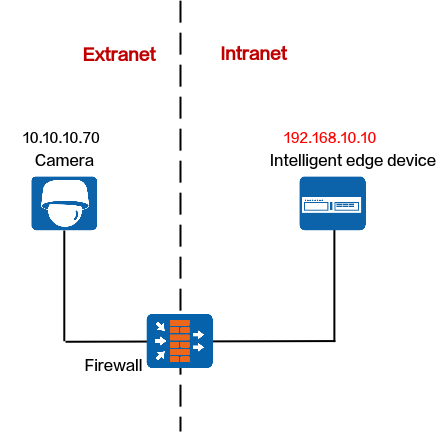
Network
If the camera is on an extranet and the HWT-IVS1800 is on an intranet, you need to translate the IP address and port number of the HWT-IVS1800 to an extranet IP address and port number for the client to access, as shown in Figure 5-52.
Protocols That Support NAT
Registration Type |
Protocol |
Support NAT |
Procedure |
|---|---|---|---|
Passive registration |
HWSDK |
Yes |
|
ONVIF |
Yes |
||
Proactive registration |
HWSDK |
Yes |
|
GB/T 28181 |
Yes |
HWSDK (Passive Registration)
Data Plan
This section uses NAT mapping based on IP addresses and port translation as an example for data plan.
NAT based on IP address translation is relatively simple. In addition to IP address NAT on the firewall, the ports in the data plan need to be allowed in both directions. For details about how to allow ports, see the firewall documentation.
NE |
Require Configuration on the NE |
Pre-NAT IP Address |
Post-NAT IP Address |
Pre-NAT Port Number |
Post-NAT Port Number |
|---|---|---|---|---|---|
Cameras |
No |
- |
- |
-- |
- |
Firewall |
Yes |
192.168.10.10 |
10.10.10.10 |
|
NOTE:
|
HWT-IVS1800 |
Yes |
|
|
|
NOTE:
|
Configuring NAT on the Firewall
- Go to the firewall configuration page by referring to Logging In to the Firewall.
- Configure NAT based on the data plan.
- IP address NAT:
nat server name global Post-NAT IP address inside IP address of HWT-IVS1800
- IP address and port NAT
- NAT of a single IP address and a single port
TCP: nat server name protocol tcp global Post-NAT IP address Post-NAT port number inside IP address Port number unr-route
UDP: nat server name protocol udp global Post-NAT IP address Post-NAT port number inside IP address Port number unr-route
- NAT of a single IP address and multiple ports
TCP: nat server name protocol tcp global Post-NAT IP address Post-NAT start port number Post-NAT end port number inside IP address Start port number End port number unr-route
UDP: nat server name protocol udp global Post-NAT IP address Post-NAT start port number Post-NAT end port number inside IP address Start port number End port number unr-route
- NAT of a single IP address and a single port
In the preceding commands, name indicates the unique name of the NAT server. The requirements on the server name are as follows:
- It is a string of 1 to 256 case-sensitive characters and can be a combination of digits.
- It must start with a letter or digit.
- It cannot be all, vsys, or all-systems and cannot be name, global, protocol, vpn-instance, zone, or their first several characters. For example, the value cannot be n, na, or nam.
- IP address NAT:
- Run the display current-configuration command to view the NAT configuration on the firewall and determine whether the NAT configuration is correct.
To modify the NAT configuration on the firewall, run the undo nat server name command to delete the original NAT configuration and then re-configure NAT.
- Configure a security policy on the firewall.
[FW] security-policy
[FW-policy-security] rule name rule_name
[FW-policy-security-rule-policy_sec1] source-zone untrust
[FW-policy-security-rule-policy_sec1] destination-zone trust
[FW-policy-security-rule-policy_sec1] destination-address video/image management platform IP address 32
[FW-policy-security-rule-policy_sec1] action permit
[FW-policy-security-rule-policy_sec1] quit
- rule_name: name of a security policy. You can configure multiple security policies as required.
- IP address of device in the Trust security zone: pre-NAT IP address of the intranet device. If there are multiple IP addresses, configure multiple security policies.
- Optional: Configure NAT ALG.Compared with the HWT-IVS1800+firewall NAT scheme, the firewall ALG scheme occupies fewer ports.
Configure port NAT.
By default, SIP port 5060 is used. However, GB/T 28181 uses SIP port 5080. Therefore, you need to perform this step.
[FW]acl 2000
[FW-acl-basic-2000]rule permit
[FW-acl-basic-2000]quit
[FW]port-mapping sip port 5080 acl 2000
[FW]quit
- Configure firewall NAT ALG to implement proper SIP packet forwarding.
[FW] firewall interzone trust untrust
[FW-interzone-trust-untrust] detect sip
[FW-interzone-trust-untrust] quit
- Verify that the settings have taken effect.
After the cameras are successfully registered, run the display firewall session table command on the firewall to view the session table. The following information indicates that the settings have taken effect:
Current Total Sessions : 2
sip VPN:public --> public X.X.X.X:2107-->10.10.10.10:5080[192.168.10.13:5080]
- Configure a static route to the extranet IP address (for example, 10.10.10.90) on the router, with the next hop being the intranet IP address of the firewall. In this manner, the messages returned from an extranet can be forwarded to the firewall.
In most cases, you need to contact the network administrator to configure the static route.
Configuring NAT on the HWT-IVS1800
- Log in to the OMU portal as the admin user. ( Logging In to the OMU portal)
- Choose System > Advanced Configuration.
- Configure NAT information, as shown in Figure 5-68.
Table 5-62 describes the parameters.
Table 5-62 Parameter descriptionModule
Parameter
Description
PUBLIC
SNatIP
Southbound IP address of the HWT-IVS1800, which must be the same as the post-NAT IP address configured on the firewall.
DCG_NAT_LIST
List of subnets, which is used by the HWT-IVS1800 to determine whether NAT needs to be configured for IP addresses of southbound devices.
- If no user-defined NAT subnet list is configured, the system performs NAT for all IP addresses except standard subnet addresses by default.The standard private network IP address ranges are as follows:
Class A: 10.0.0.1 to 10.255.255.254
Class B: 172.16.0.1 to 172.31.255.254
Class C: 192.168.0.1 to 192.168.255.254
- If a user-defined NAT subnet list is configured, the system performs NAT for all IP addresses (including standard private IP addresses) except those in the NAT subnet list.
If there are multiple IP subnets, use semicolons (;) to separate them, for example, 192.168.1.0/24;192.168.2.0/24.
IMGUSNatPort
Post-NAT southbound port number of the IMGU of the HWT-IVS1800, which must be the same as the post-NAT port number configured on the firewall. The default port number is 9555.
OMUSHttpNatPort
Post-NAT southbound HTTP port number of the OMU of the HWT-IVS1800, which must be the same as the post-NAT port number configured on the firewall. The default port number is 8481.
OMUSHttpsNatPort
Post-NAT southbound HTTPS port number of the OMU of the HWT-IVS1800, which must be the same as the post-NAT port number configured on the firewall. The default port number is 8443.
NatSRtspPort
Post-NAT southbound port number of the MU of the HWT-IVS1800, which must be the same as the post-NAT port number configured on the firewall. The default port number is 554.
MU
TcpRecvMediaPort
The port is used by the MU of the HWT-IVS1800 to receive media streams from cameras. The system uses this configuration value and the 101 ports that follow. If you change the port number, ensure that the new port number is different from those described in the product communication matrix.
The value range is [10000,30000], and [n,n+101] cannot contain port 18531. n indicates the start port number.
UdpRecvMediaPort
The port is used by the MU of the HWT-IVS1800 to receive media streams from cameras. After the setting, the system automatically occupies the port number specified by this parameter and the following 799 port numbers. If you change the port number, ensure that the new port number is different from those described in the product communication matrix.
The value range is [10000,30000], and [n,n+799] cannot contain port 18531. The value n indicates the start port number.
- If no user-defined NAT subnet list is configured, the system performs NAT for all IP addresses except standard subnet addresses by default.
ONVIF
Data Plan
This section uses NAT mapping based on IP addresses and port translation as an example for data plan.
NAT based on IP address translation is relatively simple. In addition to IP address NAT on the firewall, the ports in the data plan need to be allowed in both directions. For details about how to allow ports, see the firewall documentation.
NE |
Require Configuration on the NE |
Pre-NAT IP Address |
Post-NAT IP Address |
Pre-NAT Port Number |
Post-NAT Port Number |
|---|---|---|---|---|---|
Cameras |
No |
- |
- |
- |
- |
Firewall |
Yes |
192.168.10.10 |
10.10.10.10 |
|
NOTE:
|
HWT-IVS1800 |
Yes |
|
|
|
NOTE:
|
Configuring NAT on the Firewall
- Go to the firewall configuration page by referring to Logging In to the Firewall.
- Configure NAT based on the data plan.
- IP address NAT:
nat server name global Post-NAT IP address inside IP address of HWT-IVS1800
- IP address and port NAT
- NAT of a single IP address and a single port
TCP: nat server name protocol tcp global Post-NAT IP address Post-NAT port number inside IP address Port number unr-route
UDP: nat server name protocol udp global Post-NAT IP address Post-NAT port number inside IP address Port number unr-route
- NAT of a single IP address and multiple ports
TCP: nat server name protocol tcp global Post-NAT IP address Post-NAT start port number Post-NAT end port number inside IP address Start port number End port number unr-route
UDP: nat server name protocol udp global Post-NAT IP address Post-NAT start port number Post-NAT end port number inside IP address Start port number End port number unr-route
- NAT of a single IP address and a single port
In the preceding commands, name indicates the unique name of the NAT server. The requirements on the server name are as follows:
- It is a string of 1 to 256 case-sensitive characters and can be a combination of digits.
- It must start with a letter or digit.
- It cannot be all, vsys, or all-systems and cannot be name, global, protocol, vpn-instance, zone, or their first several characters. For example, the value cannot be n, na, or nam.
- IP address NAT:
- Run the display current-configuration command to view the NAT configuration on the firewall and determine whether the NAT configuration is correct.
To modify the NAT configuration on the firewall, run the undo nat server name command to delete the original NAT configuration and then re-configure NAT.
- Configure a security policy on the firewall.
[FW] security-policy
[FW-policy-security] rule name rule_name
[FW-policy-security-rule-policy_sec1] source-zone untrust
[FW-policy-security-rule-policy_sec1] destination-zone trust
[FW-policy-security-rule-policy_sec1] destination-address video/image management platform IP address 32
[FW-policy-security-rule-policy_sec1] action permit
[FW-policy-security-rule-policy_sec1] quit
- rule_name: name of a security policy. You can configure multiple security policies as required.
- IP address of device in the Trust security zone: pre-NAT IP address of the intranet device. If there are multiple IP addresses, configure multiple security policies.
- Optional: Configure NAT ALG.Compared with the HWT-IVS1800+firewall NAT scheme, the firewall ALG scheme occupies fewer ports.
Configure port NAT.
By default, SIP port 5060 is used. However, GB/T 28181 uses SIP port 5080. Therefore, you need to perform this step.
[FW]acl 2000
[FW-acl-basic-2000]rule permit
[FW-acl-basic-2000]quit
[FW]port-mapping sip port 5080 acl 2000
[FW]quit
- Configure firewall NAT ALG to implement proper SIP packet forwarding.
[FW] firewall interzone trust untrust
[FW-interzone-trust-untrust] detect sip
[FW-interzone-trust-untrust] quit
- Verify that the settings have taken effect.
After the cameras are successfully registered, run the display firewall session table command on the firewall to view the session table. The following information indicates that the settings have taken effect:
Current Total Sessions : 2
sip VPN:public --> public X.X.X.X:2107-->10.10.10.10:5080[192.168.10.13:5080]
- Configure a static route to the extranet IP address (for example, 10.10.10.90) on the router, with the next hop being the intranet IP address of the firewall. In this manner, the messages returned from an extranet can be forwarded to the firewall.
In most cases, you need to contact the network administrator to configure the static route.
Configuring NAT on the HWT-IVS1800
- Log in to the OMU portal as the admin user. ( Logging In to the OMU portal)
- Choose System > Advanced Configuration.
- Configure NAT information, as shown in Figure 5-69.
Table 5-64 describes the parameters.
Table 5-64 Parameter descriptionModule
Parameter
Description
PUBLIC
SNatIP
Southbound IP address of the HWT-IVS1800, which must be the same as the post-NAT IP address configured on the firewall.
DCG_NAT_LIST
List of subnets, which is used by the HWT-IVS1800 to determine whether NAT needs to be configured for IP addresses of southbound devices.
- If no user-defined NAT subnet list is configured, the system performs NAT for all IP addresses except standard subnet addresses by default.The standard private network IP address ranges are as follows:
Class A: 10.0.0.1 to 10.255.255.254
Class B: 172.16.0.1 to 172.31.255.254
Class C: 192.168.0.1 to 192.168.255.254
- If a user-defined NAT subnet list is configured, the system performs NAT for all IP addresses (including standard private IP addresses) except those in the NAT subnet list.
If there are multiple IP subnets, use semicolons (;) to separate them, for example, 192.168.1.0/24;192.168.2.0/24.
OMUSHttpNatPort
Post-NAT southbound HTTP port number of the OMU of the HWT-IVS1800, which must be the same as the post-NAT port number configured on the firewall. The default port number is 8481.
OMUSHttpsNatPort
Post-NAT southbound HTTPS port number of the OMU of the HWT-IVS1800, which must be the same as the post-NAT port number configured on the firewall. The default port number is 8443.
NatSRtspPort
Post-NAT southbound port number of the MU of the HWT-IVS1800, which must be the same as the post-NAT port number configured on the firewall. The default port number is 554.
MU
TcpRecvMediaPort
The port is used by the MU of the HWT-IVS1800 to receive media streams from cameras. After the setting, the system automatically occupies the port number specified by this parameter and the following 101 port numbers. If you change the port number, ensure that the new port number is different from those described in the product communication matrix.
The value range is [10000,30000], and [n,n+101] cannot contain port 18531. The value n indicates the start port number.
UdpRecvMediaPort
The port is used by the MU of the HWT-IVS1800 to receive media streams from cameras. After the setting, the system automatically occupies the port number specified by this parameter and the following 799 port numbers. If you change the port number, ensure that the new port number is different from those described in the product communication matrix.
The value range is [10000,30000], and [n,n+799] cannot contain port 18531. The value n indicates the start port number.
DCG
ONVIF_NAT
Set ONVIF_NAT to 1. The default value is 0.
- 0: no
- 1: yes
Indicates whether to forcibly replace the IP address and port number obtained from the ONVIF capability set with those used for adding cameras.
- If no user-defined NAT subnet list is configured, the system performs NAT for all IP addresses except standard subnet addresses by default.
HWSDK (Proactive Registration)
Data Plan
This section uses NAT mapping based on IP addresses and port translation as an example for data plan.
NAT based on IP address translation is relatively simple. In addition to IP address NAT on the firewall, the ports in the data plan need to be allowed in both directions. For details about how to allow ports, see the firewall documentation.
NE |
Require Configuration on the NE |
Pre-NAT IP Address |
Post-NAT IP Address |
Pre-NAT Port Number |
Post-NAT Port Number |
|---|---|---|---|---|---|
Cameras |
No |
- |
- |
- |
- |
Firewall |
Yes |
192.168.10.10 |
10.10.10.10 |
|
NOTE:
|
HWT-IVS1800 |
Yes |
|
|
|
NOTE:
|
Configuring NAT on the Firewall
- Go to the firewall configuration page by referring to Logging In to the Firewall.
- Configure NAT based on the data plan.
- IP address NAT:
nat server name global Post-NAT IP address inside IP address of HWT-IVS1800
- IP address and port NAT
- NAT of a single IP address and a single port
TCP: nat server name protocol tcp global Post-NAT IP address Post-NAT port number inside IP address Port number unr-route
UDP: nat server name protocol udp global Post-NAT IP address Post-NAT port number inside IP address Port number unr-route
- NAT of a single IP address and multiple ports
TCP: nat server name protocol tcp global Post-NAT IP address Post-NAT start port number Post-NAT end port number inside IP address Start port number End port number unr-route
UDP: nat server name protocol udp global Post-NAT IP address Post-NAT start port number Post-NAT end port number inside IP address Start port number End port number unr-route
- NAT of a single IP address and a single port
In the preceding commands, name indicates the unique name of the NAT server. The requirements on the server name are as follows:
- It is a string of 1 to 256 case-sensitive characters and can be a combination of digits.
- It must start with a letter or digit.
- It cannot be all, vsys, or all-systems and cannot be name, global, protocol, vpn-instance, zone, or their first several characters. For example, the value cannot be n, na, or nam.
- IP address NAT:
- Run the display current-configuration command to view the NAT configuration on the firewall and determine whether the NAT configuration is correct.
To modify the NAT configuration on the firewall, run the undo nat server name command to delete the original NAT configuration and then re-configure NAT.
- Configure a security policy on the firewall.
[FW] security-policy
[FW-policy-security] rule name rule_name
[FW-policy-security-rule-policy_sec1] source-zone untrust
[FW-policy-security-rule-policy_sec1] destination-zone trust
[FW-policy-security-rule-policy_sec1] destination-address video/image management platform IP address 32
[FW-policy-security-rule-policy_sec1] action permit
[FW-policy-security-rule-policy_sec1] quit
- rule_name: name of a security policy. You can configure multiple security policies as required.
- IP address of device in the Trust security zone: pre-NAT IP address of the intranet device. If there are multiple IP addresses, configure multiple security policies.
- Optional: Configure NAT ALG.Compared with the HWT-IVS1800+firewall NAT scheme, the firewall ALG scheme occupies fewer ports.
Configure port NAT.
By default, SIP port 5060 is used. However, GB/T 28181 uses SIP port 5080. Therefore, you need to perform this step.
[FW]acl 2000
[FW-acl-basic-2000]rule permit
[FW-acl-basic-2000]quit
[FW]port-mapping sip port 5080 acl 2000
[FW]quit
- Configure firewall NAT ALG to implement proper SIP packet forwarding.
[FW] firewall interzone trust untrust
[FW-interzone-trust-untrust] detect sip
[FW-interzone-trust-untrust] quit
- Verify that the settings have taken effect.
After the cameras are successfully registered, run the display firewall session table command on the firewall to view the session table. The following information indicates that the settings have taken effect:
Current Total Sessions : 2
sip VPN:public --> public X.X.X.X:2107-->10.10.10.10:5080[192.168.10.13:5080]
- Configure a static route to the extranet IP address (for example, 10.10.10.90) on the router, with the next hop being the intranet IP address of the firewall. In this manner, the messages returned from an extranet can be forwarded to the firewall.
In most cases, you need to contact the network administrator to configure the static route.
Configuring NAT on the HWT-IVS1800
- Log in to the OMU portal as the admin user. ( Logging In to the OMU portal)
- Choose System > Advanced Configuration.
- Configure NAT information, as shown in Figure 5-70.
Table 5-66 describes the parameters.
Table 5-66 Parameter descriptionModule
Parameter
Description
PUBLIC
SNatIP
Southbound IP address of the HWT-IVS1800, which must be the same as the post-NAT IP address configured on the firewall.
DCG_NAT_LIST
List of subnets, which is used by the HWT-IVS1800 to determine whether NAT needs to be configured for IP addresses of southbound devices.
- If no user-defined NAT subnet list is configured, the system performs NAT for all IP addresses except standard subnet addresses by default.The standard private network IP address ranges are as follows:
Class A: 10.0.0.1 to 10.255.255.254
Class B: 172.16.0.1 to 172.31.255.254
Class C: 192.168.0.1 to 192.168.255.254
- If a user-defined NAT subnet list is configured, the system performs NAT for all IP addresses (including standard private IP addresses) except those in the NAT subnet list.
If there are multiple IP subnets, use semicolons (;) to separate them, for example, 192.168.1.0/24;192.168.2.0/24.
NatSRtspPort
Post-NAT southbound port number of the MU of the HWT-IVS1800, which must be the same as the post-NAT port number configured on the firewall. The default port number is 554.
IMGUSNatPort
Post-NAT southbound port number of the IMGU of the HWT-IVS1800, which must be the same as the post-NAT port number configured on the firewall. The default port number is 9555.
OMUSHttpNatPort
Post-NAT southbound HTTP port number of the OMU of the HWT-IVS1800, which must be the same as the post-NAT port number configured on the firewall. The default port number is 8481.
OMUSHttpsNatPort
Post-NAT southbound HTTPS port number of the OMU of the HWT-IVS1800, which must be the same as the post-NAT port number configured on the firewall. The default port number is 8443.
MU
TcpRecvMediaPort
The port is used by the MU of the HWT-IVS1800 to receive media streams from cameras. After the setting, the system automatically occupies the port number specified by this parameter and the following 101 port numbers. If you change the port number, ensure that the new port number is different from those described in the product communication matrix.
The value range is [10000,30000], and [n,n+101] cannot contain port 18531. n indicates the start port number.
UdpRecvMediaPort
The port is used by the MU of the HWT-IVS1800 to receive media streams from cameras. After the setting, the system automatically occupies the port number specified by this parameter and the following 799 port numbers. If you change the port number, ensure that the new port number is different from those described in the product communication matrix.
The value range is [10000,30000], and [n,n+799] cannot contain port 18531. n indicates the start port number.
- If no user-defined NAT subnet list is configured, the system performs NAT for all IP addresses except standard subnet addresses by default.
GB/T 28181
Data Plan
This section uses NAT mapping based on IP addresses and port translation as an example for data plan.
NAT based on IP address translation is relatively simple. In addition to IP address NAT on the firewall, the ports in the data plan need to be allowed in both directions. For details about how to allow ports, see the firewall documentation.
NE |
Require Configuration on the NE |
Pre-NAT IP Address |
Post-NAT IP Address |
Pre-NAT Port Number |
Post-NAT Port Number |
|---|---|---|---|---|---|
Cameras |
No |
- |
- |
- |
- |
Firewall |
Yes |
192.168.10.10 |
10.10.10.10 |
|
NOTE:
|
HWT-IVS1800 |
Yes |
|
|
|
NOTE:
|
Configuring NAT on the Firewall
- Go to the firewall configuration page by referring to Logging In to the Firewall.
- Configure NAT based on the data plan.
- IP address NAT:
nat server name global Post-NAT IP address inside IP address of HWT-IVS1800
- IP address and port NAT
- NAT of a single IP address and a single port
TCP: nat server name protocol tcp global Post-NAT IP address Post-NAT port number inside IP address Port number unr-route
UDP: nat server name protocol udp global Post-NAT IP address Post-NAT port number inside IP address Port number unr-route
- NAT of a single IP address and multiple ports
TCP: nat server name protocol tcp global Post-NAT IP address Post-NAT start port number Post-NAT end port number inside IP address Start port number End port number unr-route
UDP: nat server name protocol udp global Post-NAT IP address Post-NAT start port number Post-NAT end port number inside IP address Start port number End port number unr-route
- NAT of a single IP address and a single port
In the preceding commands, name indicates the unique name of the NAT server. The requirements on the server name are as follows:
- It is a string of 1 to 256 case-sensitive characters and can be a combination of digits.
- It must start with a letter or digit.
- It cannot be all, vsys, or all-systems and cannot be name, global, protocol, vpn-instance, zone, or their first several characters. For example, the value cannot be n, na, or nam.
- IP address NAT:
- Run the display current-configuration command to view the NAT configuration on the firewall and determine whether the NAT configuration is correct.
To modify the NAT configuration on the firewall, run the undo nat server name command to delete the original NAT configuration and then re-configure NAT.
- Configure a security policy on the firewall.
[FW] security-policy
[FW-policy-security] rule name rule_name
[FW-policy-security-rule-policy_sec1] source-zone untrust
[FW-policy-security-rule-policy_sec1] destination-zone trust
[FW-policy-security-rule-policy_sec1] destination-address video/image management platform IP address 32
[FW-policy-security-rule-policy_sec1] action permit
[FW-policy-security-rule-policy_sec1] quit
- rule_name: name of a security policy. You can configure multiple security policies as required.
- IP address of device in the Trust security zone: pre-NAT IP address of the intranet device. If there are multiple IP addresses, configure multiple security policies.
- Optional: Configure NAT ALG.Compared with the HWT-IVS1800+firewall NAT scheme, the firewall ALG scheme occupies fewer ports.
Configure port NAT.
By default, SIP port 5060 is used. However, GB/T 28181 uses SIP port 5080. Therefore, you need to perform this step.
[FW]acl 2000
[FW-acl-basic-2000]rule permit
[FW-acl-basic-2000]quit
[FW]port-mapping sip port 5080 acl 2000
[FW]quit
- Configure firewall NAT ALG to implement proper SIP packet forwarding.
[FW] firewall interzone trust untrust
[FW-interzone-trust-untrust] detect sip
[FW-interzone-trust-untrust] quit
- Verify that the settings have taken effect.
After the cameras are successfully registered, run the display firewall session table command on the firewall to view the session table. The following information indicates that the settings have taken effect:
Current Total Sessions : 2
sip VPN:public --> public X.X.X.X:2107-->10.10.10.10:5080[192.168.10.13:5080]
- Configure a static route to the extranet IP address (for example, 10.10.10.90) on the router, with the next hop being the intranet IP address of the firewall. In this manner, the messages returned from an extranet can be forwarded to the firewall.
In most cases, you need to contact the network administrator to configure the static route.
Configuring NAT on the HWT-IVS1800
- Log in to the OMU portal as the admin user. ( Logging In to the OMU portal)
- Choose System > Advanced Configuration.
- Configure NAT information, as shown in Figure 5-71.
Table 5-68 describes the parameters.
Table 5-68 Parameter descriptionModule
Parameter
Description
PUBLIC
SNatIP
Southbound IP address of the HWT-IVS1800, which must be the same as the post-NAT IP address configured on the firewall.
DCG_NAT_LIST
List of subnets, which is used by the HWT-IVS1800 to determine whether NAT needs to be configured for IP addresses of southbound devices.
- If no user-defined NAT subnet list is configured, the system performs NAT for all IP addresses except standard subnet addresses by default.The standard private network IP address ranges are as follows:
Class A: 10.0.0.1 to 10.255.255.254
Class B: 172.16.0.1 to 172.31.255.254
Class C: 192.168.0.1 to 192.168.255.254
- If a user-defined NAT subnet list is configured, the system performs NAT for all IP addresses (including standard private IP addresses) except those in the NAT subnet list.
If there are multiple IP subnets, use semicolons (;) to separate them, for example, 192.168.1.0/24;192.168.2.0/24.
NatSRtspPort
Post-NAT southbound port number of the MU of the HWT-IVS1800, which must be the same as the post-NAT port number configured on the firewall. The default port number is 554.
OMUSHttpNatPort
Post-NAT southbound HTTP port number of the OMU of the HWT-IVS1800, which must be the same as the post-NAT port number configured on the firewall. The default port number is 8481.
OMUSHttpsNatPort
Post-NAT southbound HTTPS port number of the OMU of the HWT-IVS1800, which must be the same as the post-NAT port number configured on the firewall. The default port number is 8443.
MU
TcpRecvMediaPort
The port is used by the MU of the HWT-IVS1800 to receive media streams from cameras. After the setting, the system automatically occupies the port number specified by this parameter and the following 101 port numbers. If you change the port number, ensure that the new port number is different from those described in the product communication matrix.
The value range is [10000,30000], and [n,n+101] cannot contain port 18531. The value n indicates the start port number.
UdpRecvMediaPort
The port is used by the MU of the HWT-IVS1800 to receive media streams from cameras. After the setting, the system automatically occupies the port number specified by this parameter and the following 799 port numbers. If you change the port number, ensure that the new port number is different from those described in the product communication matrix.
The value range is [10000,30000], and [n,n+799] cannot contain port 18531. The value n indicates the start port number.
- If no user-defined NAT subnet list is configured, the system performs NAT for all IP addresses except standard subnet addresses by default.
Cameras on an Intranet and HWT-IVS1800 on an Extranet
Context
Network
If cameras are on an intranet and the HWT-IVS1800 is on an extranet, you need to configure the network route and firewall to connect the cameras to the HWT-IVS1800.
Take the NAT configuration on the firewall as an example. On the firewall, translate camera IP addresses to those on an extranet so that the HWT-IVS1800 can connect to the cameras through their extranet IP addresses and port numbers, as shown in Figure 5-54.
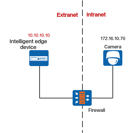
Protocols That Support NAT
Registration Type |
Protocol |
Support NAT |
Procedure |
|---|---|---|---|
Passive registration NOTE:
The iClient S100 does not allow users to add multiple cameras with the same IP address. |
ONVIF NOTE:
must support NAT. |
Yes |
|
Proactive registration |
HWSDK |
Yes |
|
GB/T 28181 |
Yes |
ONVIF
Data Plan
NE |
Require Configuration on the NE |
Pre-NAT IP Address |
Post-NAT IP Address |
Pre-NAT Port Number |
Post-NAT Port Number |
|---|---|---|---|---|---|
Cameras |
Yes |
For details, see the camera product documentation. |
|||
Firewall |
Yes |
For details, see the camera product documentation. |
|||
HWT-IVS1800 |
Yes |
- |
- |
- |
- |
Configurations on the HWT-IVS1800
- Log in to the OMU portal as the admin user. ( Logging In to the OMU portal)
- Choose System > Advanced Configuration.
- Set ONVIF_NAT to 1, as shown in Figure 5-73.
In the port mapping on the firewall, the external RTSP port must be the same as the internal RTSP port. (You need to change the camera's RTSP port to the post-NAT port.)

HWSDK (Proactive Registration)
Data Plan
NE |
Require Configuration on the NE |
Pre-NAT IP Address |
Post-NAT IP Address |
Pre-NAT Port Number |
Post-NAT Port Number |
|---|---|---|---|---|---|
Cameras |
Yes |
For details, see the camera product documentation. |
|||
Firewall |
Yes |
For details, see the camera product documentation. |
|||
HWT-IVS1800 |
No |
- |
- |
- |
- |
GB/T 28181
Data Plan
NE |
Require Configuration on the NE |
Pre-NAT IP Address |
Post-NAT IP Address |
Pre-NAT Port Number |
Post-NAT Port Number |
|---|---|---|---|---|---|
Cameras |
Yes |
For details, see the camera product documentation. |
|||
Firewall |
Yes |
For details, see the camera product documentation. |
|||
HWT-IVS1800 |
No |
- |
- |
- |
- |
Cameras and HWT-IVS1800 on Different Intranets
Context
Network
If cameras and the HWT-IVS1800 are on different intranets, you need to configure NAT for the cameras and HWT-IVS1800 respectively. After NAT is configured for the cameras and HWT-IVS1800, the cameras can connect to the HWT-IVS1800 through its extranet IP address, as shown in Figure 5-55.
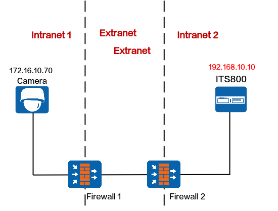
Protocols That Support NAT
Registration Type |
Protocol |
Support NAT |
Procedure |
|---|---|---|---|
Passive registration NOTE:
The iClient S100 does not allow users to add multiple cameras with the same IP address. |
ONVIF NOTE:
must support NAT. |
Yes |
|
Proactive registration |
HWSDK |
Yes |
|
GB/T 28181 |
Yes |
ONVIF
Data Plan
This section uses NAT mapping based on IP addresses and port translation as an example for data plan.
NAT based on IP address translation is relatively simple. In addition to IP address NAT on the firewall, the ports in the data plan need to be allowed in both directions. For details about how to allow ports, see the firewall documentation.
NE |
Require Configuration on the NE |
Pre-NAT IP Address |
Post-NAT IP Address |
Pre-NAT Port Number |
Post-NAT Port Number |
|---|---|---|---|---|---|
Cameras |
Yes |
must support NAT. Static IP addresses must be configured for cameras. For details, see the camera product documentation. |
|||
Firewall 1 |
Yes |
For details, see the camera product documentation. |
|||
Firewall 2 |
Yes |
192.168.10.10 |
10.10.10.10 |
|
NOTE:
|
HWT-IVS1800 |
Yes |
|
|
|
NOTE:
|
Configuring NAT on Firewall 2
- Go to the firewall configuration page by referring to Logging In to the Firewall.
- Configure NAT based on the data plan.
- IP address NAT:
nat server name global Post-NAT IP address inside IP address of HWT-IVS1800
- IP address and port NAT
- NAT of a single IP address and a single port
TCP: nat server name protocol tcp global Post-NAT IP address Post-NAT port number inside IP address Port number unr-route
UDP: nat server name protocol udp global Post-NAT IP address Post-NAT port number inside IP address Port number unr-route
- NAT of a single IP address and multiple ports
TCP: nat server name protocol tcp global Post-NAT IP address Post-NAT start port number Post-NAT end port number inside IP address Start port number End port number unr-route
UDP: nat server name protocol udp global Post-NAT IP address Post-NAT start port number Post-NAT end port number inside IP address Start port number End port number unr-route
- NAT of a single IP address and a single port
In the preceding commands, name indicates the unique name of the NAT server. The requirements on the server name are as follows:
- It is a string of 1 to 256 case-sensitive characters and can be a combination of digits.
- It must start with a letter or digit.
- It cannot be all, vsys, or all-systems and cannot be name, global, protocol, vpn-instance, zone, or their first several characters. For example, the value cannot be n, na, or nam.
- IP address NAT:
- Run the display current-configuration command to view the NAT configuration on the firewall and determine whether the NAT configuration is correct.
To modify the NAT configuration on the firewall, run the undo nat server name command to delete the original NAT configuration and then re-configure NAT.
- Configure a security policy on the firewall.
[FW] security-policy
[FW-policy-security] rule name rule_name
[FW-policy-security-rule-policy_sec1] source-zone untrust
[FW-policy-security-rule-policy_sec1] destination-zone trust
[FW-policy-security-rule-policy_sec1] destination-address video/image management platform IP address 32
[FW-policy-security-rule-policy_sec1] action permit
[FW-policy-security-rule-policy_sec1] quit
- rule_name: name of a security policy. You can configure multiple security policies as required.
- IP address of device in the Trust security zone: pre-NAT IP address of the intranet device. If there are multiple IP addresses, configure multiple security policies.
- Optional: Configure NAT ALG.Compared with the HWT-IVS1800+firewall NAT scheme, the firewall ALG scheme occupies fewer ports.
Configure port NAT.
By default, SIP port 5060 is used. However, GB/T 28181 uses SIP port 5080. Therefore, you need to perform this step.
[FW]acl 2000
[FW-acl-basic-2000]rule permit
[FW-acl-basic-2000]quit
[FW]port-mapping sip port 5080 acl 2000
[FW]quit
- Configure firewall NAT ALG to implement proper SIP packet forwarding.
[FW] firewall interzone trust untrust
[FW-interzone-trust-untrust] detect sip
[FW-interzone-trust-untrust] quit
- Verify that the settings have taken effect.
After the cameras are successfully registered, run the display firewall session table command on the firewall to view the session table. The following information indicates that the settings have taken effect:
Current Total Sessions : 2
sip VPN:public --> public X.X.X.X:2107-->10.10.10.10:5080[192.168.10.13:5080]
- Configure a static route to the extranet IP address (for example, 10.10.10.90) on the router, with the next hop being the intranet IP address of the firewall. In this manner, the messages returned from an extranet can be forwarded to the firewall.
In most cases, you need to contact the network administrator to configure the static route.
Configuring NAT on the HWT-IVS1800
- Log in to the OMU portal as the admin user. ( Logging In to the OMU portal)
- Choose System > Advanced Configuration.
- Configure NAT information, as shown in Figure 5-75.
Table 5-75 describes the parameters.
Table 5-75 Parameter descriptionModule
Parameter
Description
PUBLIC
SNatIP
Southbound IP address of the HWT-IVS1800, which must be the same as the post-NAT IP address configured on the firewall.
DCG_NAT_LIST
List of subnets, which is used by the HWT-IVS1800 to determine whether NAT needs to be configured for IP addresses of southbound devices.
- If no user-defined NAT subnet list is configured, the system performs NAT for all IP addresses except standard subnet addresses by default.The standard private network IP address ranges are as follows:
Class A: 10.0.0.1 to 10.255.255.254
Class B: 172.16.0.1 to 172.31.255.254
Class C: 192.168.0.1 to 192.168.255.254
- If a user-defined NAT subnet list is configured, the system performs NAT for all IP addresses (including standard private IP addresses) except those in the NAT subnet list.
If there are multiple IP subnets, use semicolons (;) to separate them, for example, 192.168.1.0/24;192.168.2.0/24.
OMUSHttpNatPort
Post-NAT southbound HTTP port number of the OMU of the HWT-IVS1800, which must be the same as the post-NAT port number configured on the firewall. The default port number is 8481.
OMUSHttpsNatPort
Post-NAT southbound HTTPS port number of the OMU of the HWT-IVS1800, which must be the same as the post-NAT port number configured on the firewall. The default port number is 8443.
NatSRtspPort
Post-NAT southbound port number of the MU of the HWT-IVS1800, which must be the same as the post-NAT port number configured on the firewall. The default port number is 554.
MU
TcpRecvMediaPort
The port is used by the MU of the HWT-IVS1800 to receive media streams from cameras. After the setting, the system automatically occupies the port number specified by this parameter and the following 101 port numbers. If you change the port number, ensure that the new port number is different from those described in the product communication matrix.
The value range is [10000,30000], and [n,n+101] cannot contain port 18531. The value n indicates the start port number.
UdpRecvMediaPort
The port is used by the MU of the HWT-IVS1800 to receive media streams from cameras. After the setting, the system automatically occupies the port number specified by this parameter and the following 799 port numbers. If you change the port number, ensure that the new port number is different from those described in the product communication matrix.
The value range is [10000,30000], and [n,n+799] cannot contain port 18531. The value n indicates the start port number.
DCG
ONVIF_NAT
Set ONVIF_NAT to 1. The default value is 0.
- 0: no
- 1: yes
Indicates whether to forcibly replace the IP address and port number obtained from the ONVIF capability set with those used for adding cameras.
- If no user-defined NAT subnet list is configured, the system performs NAT for all IP addresses except standard subnet addresses by default.
HWSDK (Proactive Registration)
Data Plan
This section uses NAT mapping based on IP addresses and port translation as an example for data plan.
NAT based on IP address translation is relatively simple. In addition to IP address NAT on the firewall, the ports in the data plan need to be allowed in both directions. For details about how to allow ports, see the firewall documentation.
NE |
Require Configuration on the NE |
Pre-NAT IP Address |
Post-NAT IP Address |
Pre-NAT Port Number |
Post-NAT Port Number |
|---|---|---|---|---|---|
Cameras |
Yes |
Static IP addresses must be configured for cameras. For details, see the camera product documentation. |
|||
Firewall 1 |
Yes |
For details, see the camera product documentation. |
|||
Firewall 2 |
Yes |
192.168.10.10 |
10.10.10.10 |
|
NOTE:
|
HWT-IVS1800 |
Yes |
|
|
|
NOTE:
|
Configuring NAT on Firewall 2
- Go to the firewall configuration page by referring to Logging In to the Firewall.
- Configure NAT based on the data plan.
- IP address NAT:
nat server name global Post-NAT IP address inside IP address of HWT-IVS1800
- IP address and port NAT
- NAT of a single IP address and a single port
TCP: nat server name protocol tcp global Post-NAT IP address Post-NAT port number inside IP address Port number unr-route
UDP: nat server name protocol udp global Post-NAT IP address Post-NAT port number inside IP address Port number unr-route
- NAT of a single IP address and multiple ports
TCP: nat server name protocol tcp global Post-NAT IP address Post-NAT start port number Post-NAT end port number inside IP address Start port number End port number unr-route
UDP: nat server name protocol udp global Post-NAT IP address Post-NAT start port number Post-NAT end port number inside IP address Start port number End port number unr-route
- NAT of a single IP address and a single port
In the preceding commands, name indicates the unique name of the NAT server. The requirements on the server name are as follows:
- It is a string of 1 to 256 case-sensitive characters and can be a combination of digits.
- It must start with a letter or digit.
- It cannot be all, vsys, or all-systems and cannot be name, global, protocol, vpn-instance, zone, or their first several characters. For example, the value cannot be n, na, or nam.
- IP address NAT:
- Run the display current-configuration command to view the NAT configuration on the firewall and determine whether the NAT configuration is correct.
To modify the NAT configuration on the firewall, run the undo nat server name command to delete the original NAT configuration and then re-configure NAT.
- Configure a security policy on the firewall.
[FW] security-policy
[FW-policy-security] rule name rule_name
[FW-policy-security-rule-policy_sec1] source-zone untrust
[FW-policy-security-rule-policy_sec1] destination-zone trust
[FW-policy-security-rule-policy_sec1] destination-address video/image management platform IP address 32
[FW-policy-security-rule-policy_sec1] action permit
[FW-policy-security-rule-policy_sec1] quit
- rule_name: name of a security policy. You can configure multiple security policies as required.
- IP address of device in the Trust security zone: pre-NAT IP address of the intranet device. If there are multiple IP addresses, configure multiple security policies.
- Optional: Configure NAT ALG.Compared with the HWT-IVS1800+firewall NAT scheme, the firewall ALG scheme occupies fewer ports.
Configure port NAT.
By default, SIP port 5060 is used. However, GB/T 28181 uses SIP port 5080. Therefore, you need to perform this step.
[FW]acl 2000
[FW-acl-basic-2000]rule permit
[FW-acl-basic-2000]quit
[FW]port-mapping sip port 5080 acl 2000
[FW]quit
- Configure firewall NAT ALG to implement proper SIP packet forwarding.
[FW] firewall interzone trust untrust
[FW-interzone-trust-untrust] detect sip
[FW-interzone-trust-untrust] quit
- Verify that the settings have taken effect.
After the cameras are successfully registered, run the display firewall session table command on the firewall to view the session table. The following information indicates that the settings have taken effect:
Current Total Sessions : 2
sip VPN:public --> public X.X.X.X:2107-->10.10.10.10:5080[192.168.10.13:5080]
- Configure a static route to the extranet IP address (for example, 10.10.10.90) on the router, with the next hop being the intranet IP address of the firewall. In this manner, the messages returned from an extranet can be forwarded to the firewall.
In most cases, you need to contact the network administrator to configure the static route.
Configuring NAT on the HWT-IVS1800
- Log in to the OMU portal as the admin user. ( Logging In to the OMU portal)
- Choose System > Advanced Configuration.
- Configure NAT information, as shown in Figure 5-76.
Table 5-77 describes the parameters.
Table 5-77 Parameter descriptionModule
Parameter
Description
PUBLIC
SNatIP
Southbound IP address of the HWT-IVS1800, which must be the same as the post-NAT IP address configured on the firewall.
DCG_NAT_LIST
List of subnets, which is used by the HWT-IVS1800 to determine whether NAT needs to be configured for IP addresses of southbound devices.
- If no user-defined NAT subnet list is configured, the system performs NAT for all IP addresses except standard subnet addresses by default.The standard private network IP address ranges are as follows:
Class A: 10.0.0.1 to 10.255.255.254
Class B: 172.16.0.1 to 172.31.255.254
Class C: 192.168.0.1 to 192.168.255.254
- If a user-defined NAT subnet list is configured, the system performs NAT for all IP addresses (including standard private IP addresses) except those in the NAT subnet list.
If there are multiple IP subnets, use semicolons (;) to separate them, for example, 192.168.1.0/24;192.168.2.0/24.
NatSRtspPort
Post-NAT southbound port number of the MU of the HWT-IVS1800, which must be the same as the post-NAT port number configured on the firewall. The default port number is 554.
IMGUSNatPort
Post-NAT southbound port number of the IMGU of the HWT-IVS1800, which must be the same as the post-NAT port number configured on the firewall. The default port number is 9555.
OMUSHttpNatPort
Post-NAT southbound HTTP port number of the OMU of the HWT-IVS1800, which must be the same as the post-NAT port number configured on the firewall. The default port number is 8481.
OMUSHttpsNatPort
Post-NAT southbound HTTPS port number of the OMU of the HWT-IVS1800, which must be the same as the post-NAT port number configured on the firewall. The default port number is 8443.
MU
TcpRecvMediaPort
The port is used by the MU of the HWT-IVS1800 to receive media streams from cameras. After the setting, the system automatically occupies the port number specified by this parameter and the following 101 port numbers. If you change the port number, ensure that the new port number is different from those described in the product communication matrix.
The value range is [10000,30000], and [n,n+101] cannot contain port 18531. n indicates the start port number.
UdpRecvMediaPort
The port is used by the MU of the HWT-IVS1800 to receive media streams from cameras. After the setting, the system automatically occupies the port number specified by this parameter and the following 799 port numbers. If you change the port number, ensure that the new port number is different from those described in the product communication matrix.
The value range is [10000,30000], and [n,n+799] cannot contain port 18531. n indicates the start port number.
- If no user-defined NAT subnet list is configured, the system performs NAT for all IP addresses except standard subnet addresses by default.
GB/T 28181
Data Plan
This section uses NAT mapping based on IP addresses and port translation as an example for data plan.
NAT based on IP address translation is relatively simple. In addition to IP address NAT on the firewall, the ports in the data plan need to be allowed in both directions. For details about how to allow ports, see the firewall documentation.
NE |
Require Configuration on the NE |
Pre-NAT IP Address |
Post-NAT IP Address |
Pre-NAT Port Number |
Post-NAT Port Number |
|---|---|---|---|---|---|
Cameras |
Yes |
Static IP addresses must be configured for cameras. For details, see the camera product documentation. |
|||
Firewall 1 |
Yes |
For details, see the camera product documentation. |
|||
Firewall 2 |
Yes |
192.168.10.10 |
10.10.10.10 |
|
NOTE:
|
HWT-IVS1800 |
Yes |
|
|
|
NOTE:
|
Configuring NAT on Firewall 2
- Go to the firewall configuration page by referring to Logging In to the Firewall.
- Configure NAT based on the data plan.
- IP address NAT:
nat server name global Post-NAT IP address inside IP address of HWT-IVS1800
- IP address and port NAT
- NAT of a single IP address and a single port
TCP: nat server name protocol tcp global Post-NAT IP address Post-NAT port number inside IP address Port number unr-route
UDP: nat server name protocol udp global Post-NAT IP address Post-NAT port number inside IP address Port number unr-route
- NAT of a single IP address and multiple ports
TCP: nat server name protocol tcp global Post-NAT IP address Post-NAT start port number Post-NAT end port number inside IP address Start port number End port number unr-route
UDP: nat server name protocol udp global Post-NAT IP address Post-NAT start port number Post-NAT end port number inside IP address Start port number End port number unr-route
- NAT of a single IP address and a single port
In the preceding commands, name indicates the unique name of the NAT server. The requirements on the server name are as follows:
- It is a string of 1 to 256 case-sensitive characters and can be a combination of digits.
- It must start with a letter or digit.
- It cannot be all, vsys, or all-systems and cannot be name, global, protocol, vpn-instance, zone, or their first several characters. For example, the value cannot be n, na, or nam.
- IP address NAT:
- Run the display current-configuration command to view the NAT configuration on the firewall and determine whether the NAT configuration is correct.
To modify the NAT configuration on the firewall, run the undo nat server name command to delete the original NAT configuration and then re-configure NAT.
- Configure a security policy on the firewall.
[FW] security-policy
[FW-policy-security] rule name rule_name
[FW-policy-security-rule-policy_sec1] source-zone untrust
[FW-policy-security-rule-policy_sec1] destination-zone trust
[FW-policy-security-rule-policy_sec1] destination-address video/image management platform IP address 32
[FW-policy-security-rule-policy_sec1] action permit
[FW-policy-security-rule-policy_sec1] quit
- rule_name: name of a security policy. You can configure multiple security policies as required.
- IP address of device in the Trust security zone: pre-NAT IP address of the intranet device. If there are multiple IP addresses, configure multiple security policies.
- Optional: Configure NAT ALG.Compared with the HWT-IVS1800+firewall NAT scheme, the firewall ALG scheme occupies fewer ports.
Configure port NAT.
By default, SIP port 5060 is used. However, GB/T 28181 uses SIP port 5080. Therefore, you need to perform this step.
[FW]acl 2000
[FW-acl-basic-2000]rule permit
[FW-acl-basic-2000]quit
[FW]port-mapping sip port 5080 acl 2000
[FW]quit
- Configure firewall NAT ALG to implement proper SIP packet forwarding.
[FW] firewall interzone trust untrust
[FW-interzone-trust-untrust] detect sip
[FW-interzone-trust-untrust] quit
- Verify that the settings have taken effect.
After the cameras are successfully registered, run the display firewall session table command on the firewall to view the session table. The following information indicates that the settings have taken effect:
Current Total Sessions : 2
sip VPN:public --> public X.X.X.X:2107-->10.10.10.10:5080[192.168.10.13:5080]
- Configure a static route to the extranet IP address (for example, 10.10.10.90) on the router, with the next hop being the intranet IP address of the firewall. In this manner, the messages returned from an extranet can be forwarded to the firewall.
In most cases, you need to contact the network administrator to configure the static route.
Configuring NAT on the HWT-IVS1800
- Log in to the OMU portal as the admin user. ( Logging In to the OMU portal)
- Choose System > Advanced Configuration.
- Configure NAT information, as shown in Figure 5-77.
Table 5-79 describes the parameters.
Table 5-79 Parameter descriptionModule
Parameter
Description
PUBLIC
SNatIP
Southbound IP address of the HWT-IVS1800, which must be the same as the post-NAT IP address configured on the firewall.
DCG_NAT_LIST
List of subnets, which is used by the HWT-IVS1800 to determine whether NAT needs to be configured for IP addresses of southbound devices.
- If no user-defined NAT subnet list is configured, the system performs NAT for all IP addresses except standard subnet addresses by default.The standard private network IP address ranges are as follows:
Class A: 10.0.0.1 to 10.255.255.254
Class B: 172.16.0.1 to 172.31.255.254
Class C: 192.168.0.1 to 192.168.255.254
- If a user-defined NAT subnet list is configured, the system performs NAT for all IP addresses (including standard private IP addresses) except those in the NAT subnet list.
If there are multiple IP subnets, use semicolons (;) to separate them, for example, 192.168.1.0/24;192.168.2.0/24.
NatSRtspPort
Post-NAT southbound port number of the MU of the HWT-IVS1800, which must be the same as the post-NAT port number configured on the firewall. The default port number is 554.
OMUSHttpNatPort
Post-NAT southbound HTTP port number of the OMU of the HWT-IVS1800, which must be the same as the post-NAT port number configured on the firewall. The default port number is 8481.
OMUSHttpsNatPort
Post-NAT southbound HTTPS port number of the OMU of the HWT-IVS1800, which must be the same as the post-NAT port number configured on the firewall. The default port number is 8443.
MU
TcpRecvMediaPort
The port is used by the MU of the HWT-IVS1800 to receive media streams from cameras. After the setting, the system automatically occupies the port number specified by this parameter and the following 101 port numbers. If you change the port number, ensure that the new port number is different from those described in the product communication matrix.
The value range is [10000,30000], and [n,n+101] cannot contain port 18531. The value n indicates the start port number.
UdpRecvMediaPort
The port is used by the MU of the HWT-IVS1800 to receive media streams from cameras. After the setting, the system automatically occupies the port number specified by this parameter and the following 799 port numbers. If you change the port number, ensure that the new port number is different from those described in the product communication matrix.
The value range is [10000,30000], and [n,n+799] cannot contain port 18531. The value n indicates the start port number.
- If no user-defined NAT subnet list is configured, the system performs NAT for all IP addresses except standard subnet addresses by default.
- Application Limitations
- NAT Network Between the iClient S100 and HWT-IVS1800
- NAT Network Between the HWT-IVS1800 and the Upper-Level Video and Image Management Platform
- NAT-based Networking of the HWT-IVS1800 and Cameras